Development of RT Component
Making an OpenCV RT-Component (Flip component)
Making an OpenCV RT-Component (Flip component)
This section describes creating an RT-Component to invert an image using the OpenCV library and VC9:- The cvFlip() function
- Component outline
- Operating and development environment
- Generate the Flip component template
- Implement the component activities
- Test the component
The cvFlip() function
The cvFlip() function flips a 2D array (i.e. an image) on the vertical axis, horizontal axis, or both axes at the same time.
 void cvFlip(IplImage* src, IplImage* dst=NULL, int flip_mode=0);
 #define cvMirror cvFlip

 src       Input array
 dst       Output array. If dst is NULL, the result will be written into src.
 flip_mode Flag setting the axes to flip on.
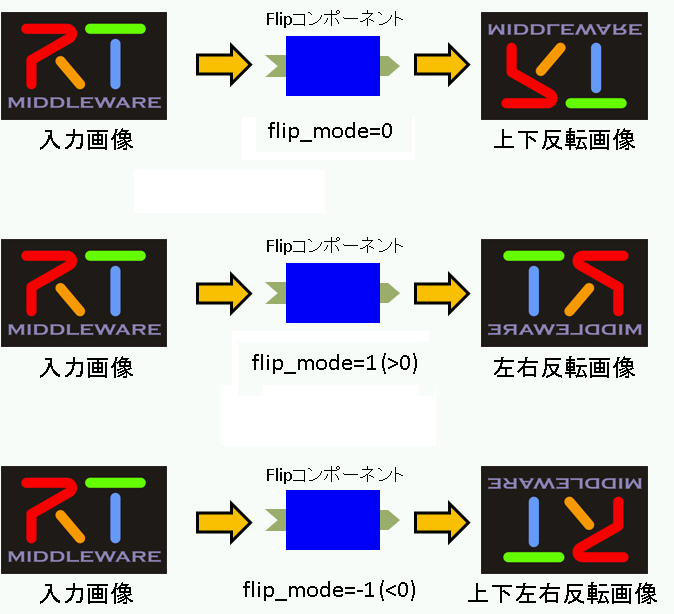
  flip_mode = 0: Flip on the X axis (swap top and bottom)
  flip_mode > 0: Flip on the Y axis (swap left and right)
  flip_mode < 0: Flip on both axes
Component outline
The component will flip an image received by an InPort and output it on an OutPort.
The flip mode will be controlled by an RTC configuration parameter called "flip_mode." Set flip_mode as below:
- Flip on the X axis: 0
- Flip on the Y axis: 1
- Flip on both axes: -1
The specification of the component we will create is as follows:
- InPort
- Captured image data (TimedOctetSeq)
- OutPort
- Flipped image data (TimedOctetSeq)
- Configuration
- Flip mode (int)
※ TimedOctetSeq is a data type specified in BasicDataType.idl from OpenRTM-aist.
※ octet is a CORBA IDL base type that can store and transmit any data in 8-bit format without transformation.
   struct Time
  {
        unsigned long sec;    // sec
        unsigned long nsec;   // nano sec
  };

   struct TimedOctetSeq
  {
        Time tm;
        sequence<octet> data;
  };
Figure 1 illustrates the effects of different flip_mode settings.
Operating environment and development environment
- OS: Windows XP SP2
- Compiler: Visual C++ 2008 Express Edition
- omniORB: version 4.1.2
- OpenCV: version 1.0
- OpenRTM-aist: version 1.0.0-RC1
- RTSystemEditor 1.0
- RTCBuilder 1.0
- Decompression tool (e.g. Lhaplus)
Generate the Flip component template
We will generate the Flip component template using RTCBuilder.
Starting RTCBuilder
Upon starting Eclipse with a new workspace, the Welcome page will be displayed.
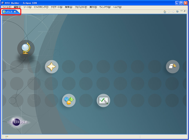
Close this Welcome screen using the close button to display the default perspective view.
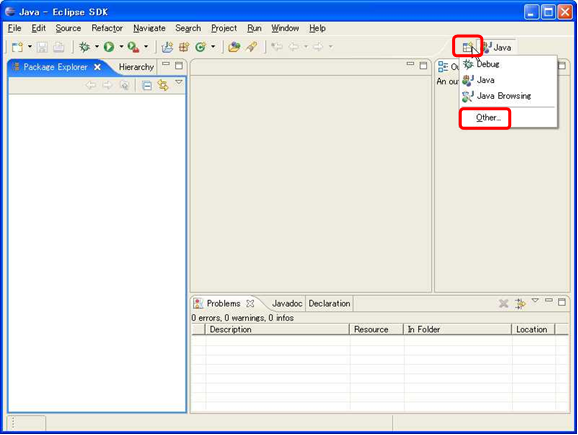
Click the "Open Perspective" button in the top right and select "Other..." from the menu.
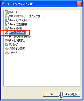
Select "RTC Builder".
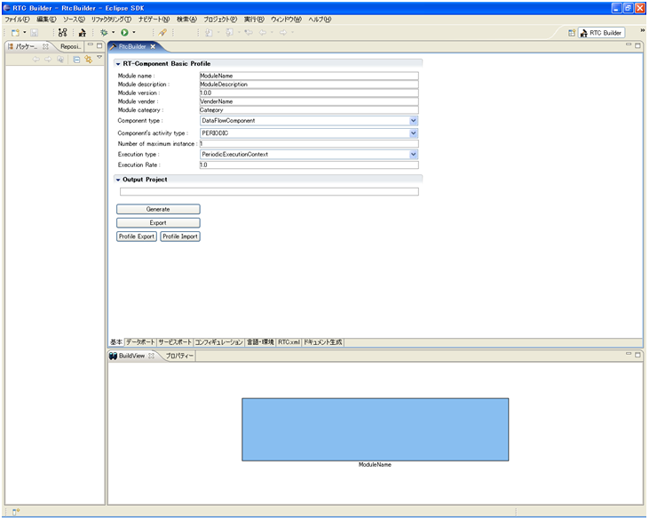
Making an RTCBuilder project
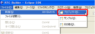
First, we will make an Eclipse project for the RT-Component. From the File menu, select "New," then "Project."
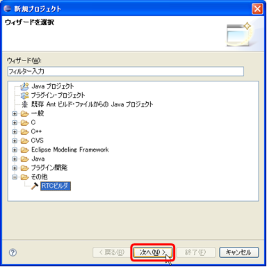
In the displayed dialog, select "Other," then "RTCBuilder" (RTC ビルダ) and click "Next".
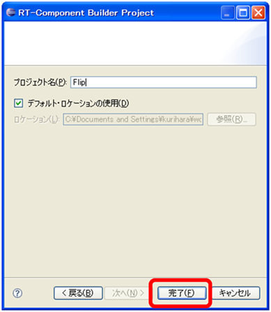
Enter a project name and click "Finish."
A project using the given name will be created and displayed in the package explorer.
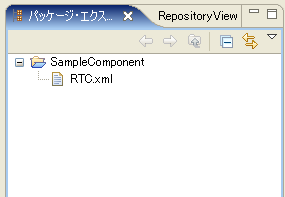
Within the generated project will be an RTC profile XML (RTC.xml) containing default values.
Starting the RTC Profile Editor
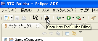
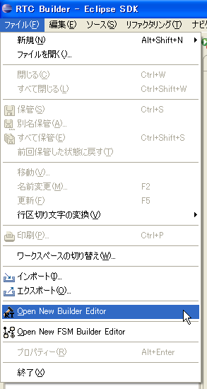
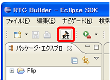
To open the RTC Profile Editor, click the "Open New RtcBuilder Editor" button on the toolbar, or select "Open New Builder Editor" from the File menu.
Data type definition files location
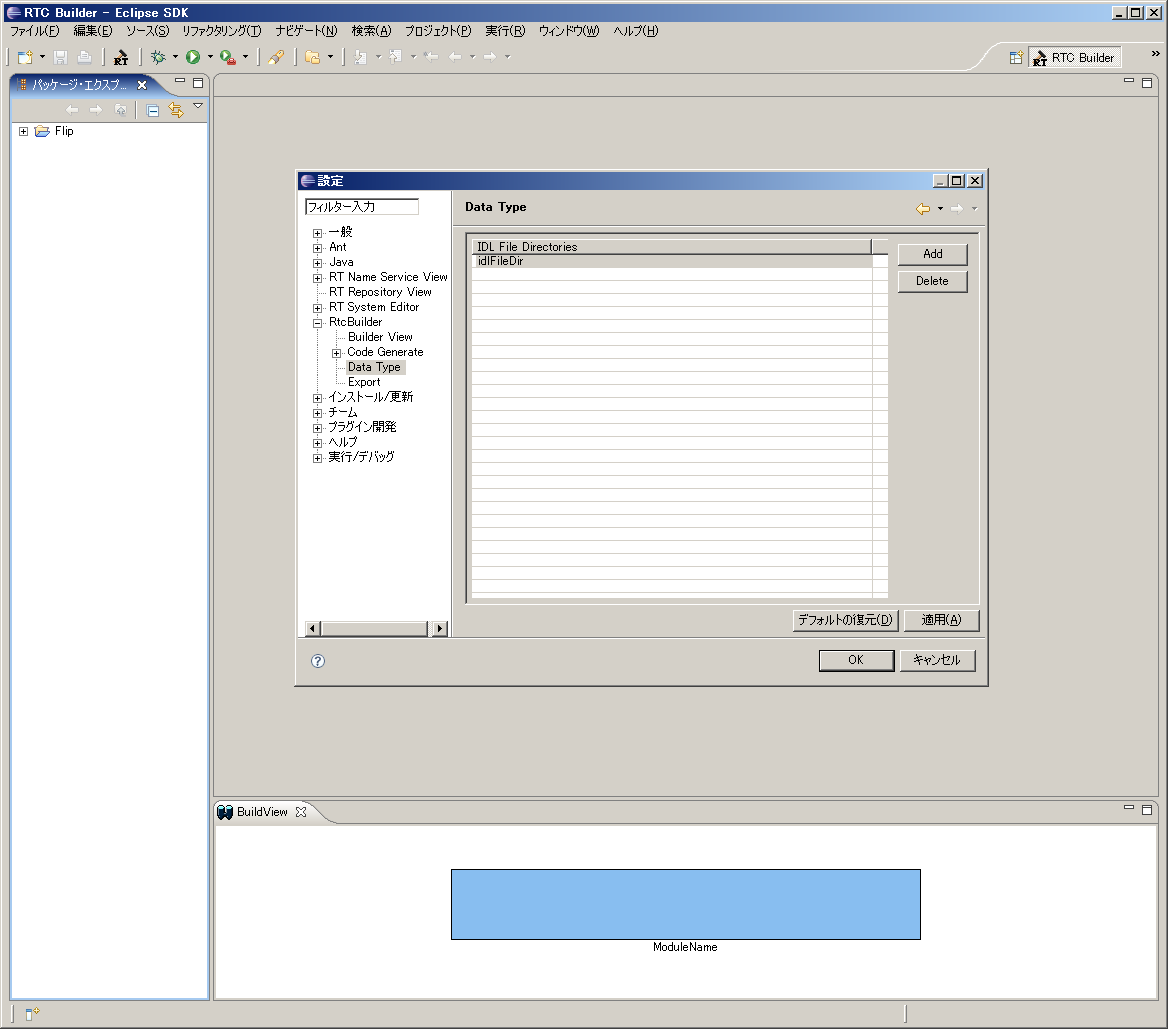
It is necessary to set the location of the IDL files that define data types used by data ports and service ports.
※ This value is valid for the entire workspace, so it does not need to be set for each project created within the same workspace.
 1. Open the settings dialog by selecting "Settings" from the "Window" menu.
 2. Expand the "RtcBuilder" branch and select "Data Type."
 3. Click the "Add" button and enter values for "IDL File Directories." IDL files included with OpenRTM-aist are installed to this path by default:

      C:\Program Files\OpenRTM-aist\1.0\rtm\idl

 4. Click the "OK" button to finish.
Entering the component profile and generating code
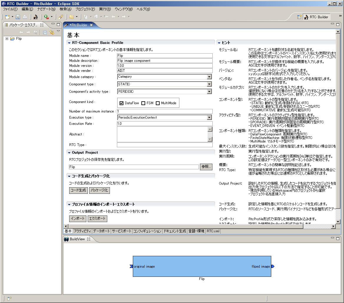
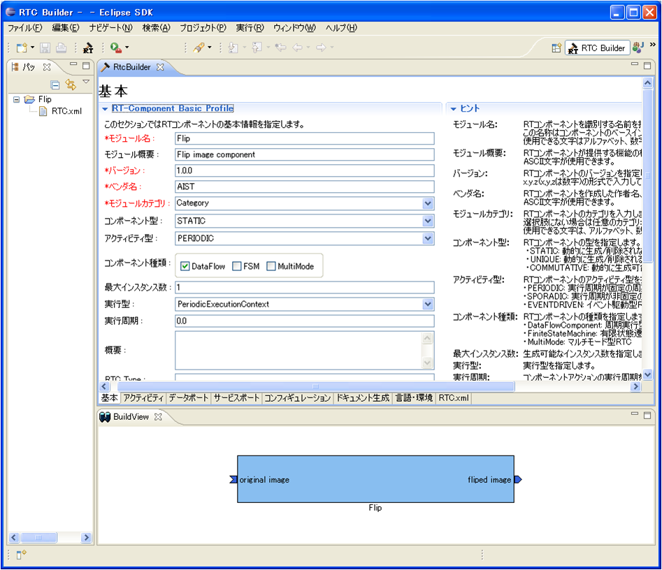
1. Select the "Basic" (基本) tab, and enter the basic component information as below.
-Module name: Flip
- Module description: Flip image component
- Module version: 1.0.0
- Module vender: AIST
- Module category: Category
- Component type: STATIC
- Component's activity type: PERIODIC
- Component kind: DataFlowComponent
- Number of maximum instance: 1
- Execution type: PeriodicExecutionContext
- Execution Rate: 1.0
-Output Project: Flip
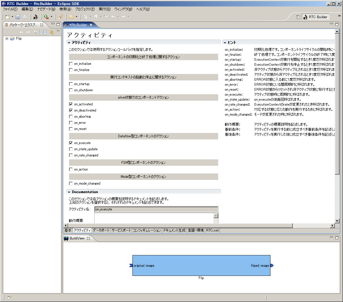
2. Select the "Activity" (アクティビティ) tab and select the action callbacks that will be used.
For the Flip component, the onActivated(), onDeactivated() and onExecute() callbacks will be used. Check them as in Figure 14.
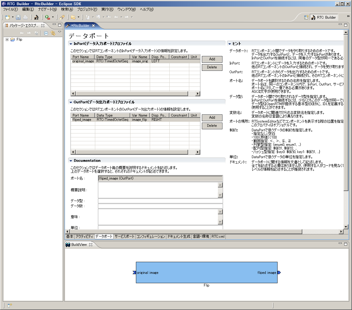
3. Select the ""Data port" (データポート) tab and enter the data port information.
-InPort Profile:
- Port Name: original_image
- Data Type: TimedOctetSeq
- Var Name: image_orig
- Disp. Position: left
-OutPort Profile: - Port Name: fliped_image
- Data Type: TimedOctetSeq
- Var Name: image_flip
- Disp. Position: right
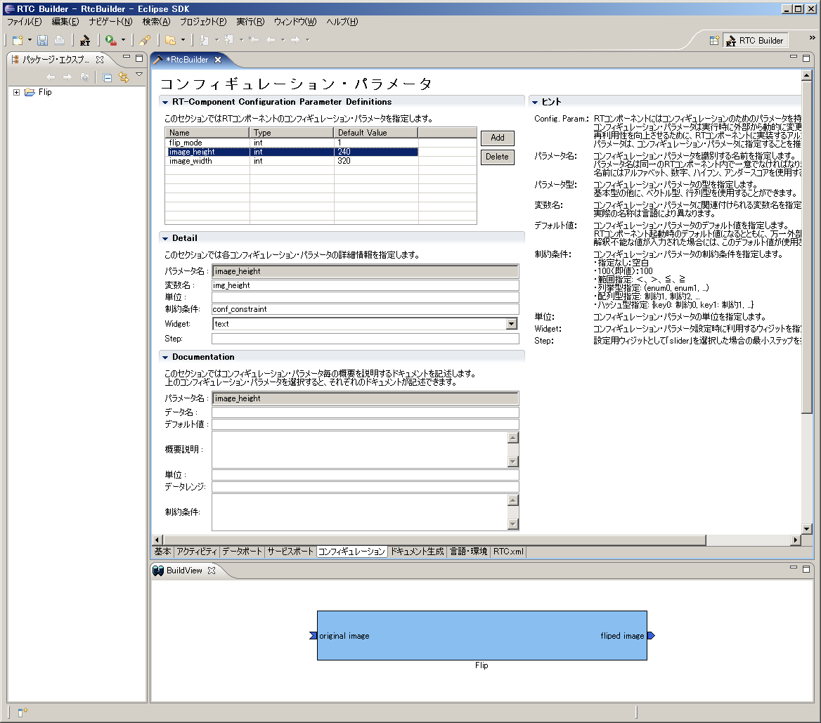
4. Select the "Configuration" (コンフィギュレーション) tab and enter the configuration parameters.
-flip_mode
- Name: flip_mode
- TYpe: int
- Default Value: 1
- Variable name: flip_mode
-image_height
- Name: image_height
- TYpe: int
- Default Value: 240
- Variable name: img_height
-image_width
- Name: image_width
- TYpe: int
- Default Value: 320
- Variable name: img_width
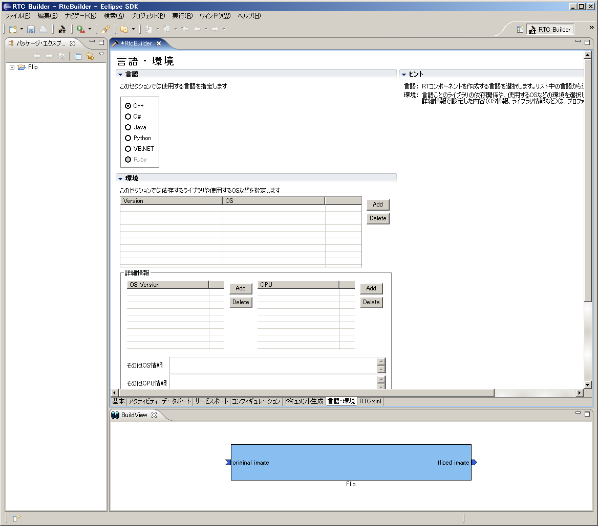
5. Select the "Language/Environment" (言語・環境) tab and choose a programming language. For the Flip component, choose C++.
6. Click the "Generate code" (コード生成) button in the "Basic" tab to generate the component template.

※ The component template code will be generated in the currently-active Eclipse workspace directory. You can check this directory by selecting "Change workspace" from the File menu.
Basic RT Component Development
Components with Data Ports
In this sample, we will create two components with data ports, and try to send and receive data between two components. The specifications of the components that we will create are as follows.
- Component1
- It has one OutPort.
- Data type of OutPort is TimedLong.
- It outputs the values input via the console to its OutPort.
- Component2
- It has one InPort.
- Data type of InPort is TimedLong.
- It has one configuration parameter.
- The configuration parameter is int type.
- The default value of configuration parameter is 1.
- It reads the value calculated by multiplying the parameter in case of reading from the InPort variable.
- It outputs the values read from InPort to the console.
Generating Source Codes Using rtc-template
To create the components with above specifications, you will prepare the following shell script named gen.sh.
 #!/bin/sh

 rtc-template -bcxx      --module-name=ConsoleIn --module-type='DataFlowComponent'      --module-desc='Console input component'      --module-version=1.0 --module-vendor='MyName'      --module-category=example      --module-comp-type=DataFlowComponent --module-act-type=SPORADIC      --module-max-inst=10 --outport=out:TimedLong

 rtc-template -bcxx      --module-name=ConsoleOut --module-type='DataFlowComponent'      --module-desc='Console output component'      --module-version=1.0 --module-vendor='MyName'      --module-category=example      --module-comp-type=DataFlowComponent --module-act-type=SPORADIC      --module-max-inst=10 --inport=in:TimedLong      --config="multiply:int:1"
The component1 is created by the first execution of rtc-template, and then the component2 is created by the next.
 > sh gen.sh
   File "ConsoleIn.h" was generated.
   File "ConsoleIn.cpp" was generated.
   File "ConsoleInComp.cpp" was generated.
   File "Makefile.ConsoleIn" was generated.
   File "README.ConsoleIn" was generated.
   File "ConsoleOut.h" was generated.
   File "ConsoleOut.cpp" was generated.
   File "ConsoleOutComp.cpp" was generated.
   File "Makefile.ConsoleOut" was generated.
   File "README.ConsoleOut" was generated.
Implementaion of ConsoleIn
The ConsoleIn component will be implemented by editing the generated source code.
ConsoleIn.h
This component waits for input and outputs the inputted value to its OutPort, when activated. Therefore, you need to implement only its onExecute member function, which is executed periodically during the active state, so uncomment the commented-out onExecute function in ConsoleIn.h:
     :snip
   // The execution action that is invoked periodically
   // former rtc_active_do()
   virtual RTC::ReturnCode_t onExecute(RTC::UniqueId ec_id);
     :snip
There is a declaration of the OutPort variables which is specified in rtc-template at the lower of ConsoleIn.h.
     :snip
   // DataOutPort declaration
   // <rtc-template block="outport_declare">
   TimedLong m_out;
   OutPort<TimedLong> m_outOut;
   // </rtc-template>
TimedLong m_out of declaration is the variable which is bound to OutPort.
OutPort<TimedLong> m_outOut of declaration is the instance of OutPort.
ConsoleIn.cpp
It is easy to implement ConsoleIn. Uncomment the commented-out onExecute function, and implement this way:
 RTC::ReturnCode_t ConsoleIn::onExecute(RTC::UniqueId ec_id)
 {
   std::cout << "Please input number: ";
   std::cin >> m_out.data;
   std::cout << "Sending to subscriber: " << m_out.data << std::endl;
   m_outOut.write();

   return RTC::RTC_OK;
}- Wait for input from a user by cin >> m_out.data
- Store the inputted value to m_out.data(long type)
- Print the inputted value for confirmation
- Output the data to OutPort by m_outOut.write()
Implementation of ConsoleOut
It is a little complicated in ConsoleOut component. You must store the result value which the data from InPort is multiplied by the configuration parameter "multiply". It can be realized by the way you set a callback object to InPort.
Callback Object
Callback Object is an object in which operator() method is defined, which is invoked when an event is occurred at buffers of InPort or OutPort. Here, we use an OnWriteConvert as the callback object, which converts data when the data are written to a buffer of InPort.
Inherit RTC::OnWriteConvert and define the next class:
 class Multiply
   : public RTC::OnWriteConvert<RTC::TimedLong>
 {
   int& m_mul;
 public:
   Multiply(int& multiply) : m_mul(multiply) {};
   RTC::TimedLong operator()(const RTC::TimedLong& value)
   {
     RTC::TimedLong ret(value);
     ret.data = value.data * m_mul;
     return ret;
   };
 };
ConsoleOut.h
Insert this callback class just after the lines of include in ConsoleOut.h. Also, declare the instance of it as a member variable of ConsoleOut class. You may insert the declaration just after private:
 private:
   Multiply m_owc;
   int dummy;
When activated, this component reads data from InPort and prints the data to the standard output. Therefore, you need to implement only its onExecute member function, which is executed periodically during the active state, so uncomment the commented-out onExecute function in the generated ConsoleOut.h:
     :snip
   // The execution action that is invoked periodically
   // former rtc_active_do()
   virtual RTC::ReturnCode_t onExecute(RTC::UniqueId ec_id);
     :snip
There are declarations of configuration variables and the InPort variables which is specified in rtc-template at the lower of ConsoleOut.h.
Since RingBuffer is used a buffer of InPort in ConsoleOut, you have to include RingBuffer.h. Around top of ConsoleIn.h, please include RingBuffer.h.
 #include <rtm/Manager.h>
 #include <rtm/DataFlowComponentBase.h>
 #include <rtm/CorbaPort.h>
 #include <rtm/DataInPort.h>
 #include <rtm/DataOutPort.h>
 #include <rtm/idl/BasicDataTypeSkel.h>
 #include <rtm/RingBuffer.h> //add this
And, modify the part of InPort<TimedLong> m_inIn, which is the default declaration of InPort, to InPort<TimedLong, RTC::RingBuffer> m_inIn for the InPort to use a RingBuffer.
     :snip
   // Configuration variable declaration
   // <rtc-template block="config_declare">
   int m_multiply;

   // </rtc-template>

   // DataInPort declaration
   // <rtc-template block="inport_declare">
   TimedLong m_in;
   InPort<TimedLong, RTC::RingBuffer> m_inIn;
int m_multiply of declaration is the variable which is bound to the configuration "multiply".
TimedLong m_in of declaration is the variable which is bound to InPort.
InPort<TimedLong, RTC::RingBuffer> m_inIn of declaration is the instance of OutPort
ConsoleOut.cpp
Add an initialization of the instance of Multiply which you have defined before in the constructor of ConsoleOut class.
 ConsoleOut::ConsoleOut(RTC::Manager* manager)
   : RTC::DataFlowComponentBase(manager),
     // <rtc-template block="initializer">
     m_inIn("in", m_in),

     // </rtc-template>
     m_owc(m_multiply),
     dummy(0)
Also, describe the code to add the callback object to InPort in the constructor.
   m_inIn.setOnWriteConvert(&m_owc); //add this
   // Registration: InPort/OutPort/Service
   // <rtc-template block="registration">
   // Set InPort buffers
   registerInPort("in", m_inIn);
Uncomment the onExecute function, and implement this way:
 RTC::ReturnCode_t ConsoleIn::onExecute(RTC::UniqueId ec_id)
 {
   if (m_inIn.isNew())
     {
       m_inIn.read();
       std::cout << "Received: " << m_in.data << std::endl;
       std::cout << "TimeStamp: " << m_in.tm.sec << "[s] ";
       std::cout << m_in.tm.nsec << "[ns]" << std::endl;
     }
   usleep(1000);

   return RTC::RTC_OK;
}- Check whether InPort has data by m_inIn.isNew()
- isNew() is a member function defined in RingBuffer
- If it has new data, load the data in the variable by m_inIn.read()
- Print the data(m_in.data)
Compile
Once you finished implementing, compile your sources as below:
 > make -f Makefile.ConsoleIn
 > make -f Makefile.ConsoleOut
In case of compile errors, check whether there are misspellings or other mistakes, and compile again.
Execute
Prepare an appropriate rtc.conf and run ConsoleInComp and ConsoleOutComp, using two terminals.
Start up RtcLink, connect the two components, and activate them.
#imgr(./figs/Manual/ConsoleInConsoleOut2.png,center,nolink)
In the terminal running ConsoleIn, a prompt Please input number: is shown, so enter an appropriate number:
 Please input number: 1
 Sending to subscriber: 1
 Please input number: 2
 Sending to subscriber: 2
 Please input number: 3
 Sending to subscriber: 3
In the other terminal, which is running ConsoleOut, results should be printed like this:
 Received: 1
 TimeStamp: 0[s] 0[ns]
 Received: 2
 TimeStamp: 0[s] 0[ns]
 Received: 3
 TimeStamp: 0[s] 0[ns]
Next, on the configuration view of RtcLink, change the multiply value to 10. Then, values inputted in ConsoleIn should be multiplied by 10 and printed like this:
 Received: 10
 TimeStamp: 0[s] 0[ns]
 Received: 20
 TimeStamp: 0[s] 0[ns]
 Received: 30
 TimeStamp: 0[s] 0[ns]
Implement the component activities
Implement the component activities
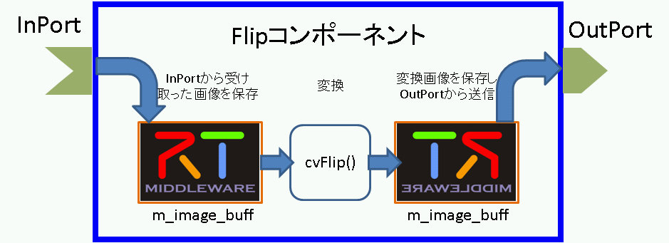
The Flip component will take image data received at its InPort, copy it into an image buffer, and use the cvFlip() function from OpenCV to transform it. The transformed data will be transmitted over the component's OutPort.
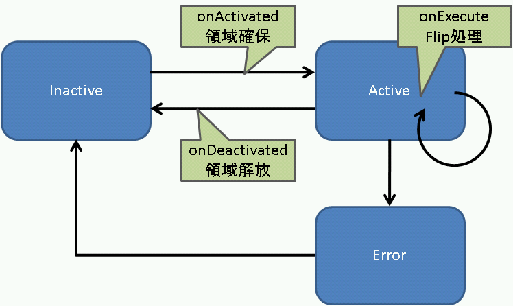
The process flow of onActivated(), onExecute() and onDeactivated() is illustrated in Figure 19.
The processing performed by onExecute() is illustrated in Figure 20.
Copy the user property sheet for OpenCV
A property sheet defines the various options (such as install path, library paths and extra link libraries) and macros necessary to compile using Visual Studio. Both RTCBuilder and rtc-template generate VC projects when they generate component templates. The generated VC project uses a property sheet to specify various options. It can also include a user-defined property sheet for any extra user-defined options.- rtm_config.vsprop: A property sheet that contains information relating to OpenRTM. Installed with OpenRTM-aist. Execute the "copyprops.bat" file in your generated project directory to copy it from the OpenRTM directory to the project directory.
- user_config.vsprops: A user-defined property sheet. The default sheet is empty. An example of its usage is given in the user_config.vsprops included with the OpenRTM USBCamera example (OpenRTM-aist/win32/OpenRTM-aist/example/USBCamera). This example sheet contains settings for OpenCV.
Copy the user_config.vsprops file given below into the Flip component's folder, or save the downloadable version into the component's folder.
※ The user_config.vsprops file that already exists in the Flip folder can be overwritten.
<?xml version="1.0" encoding="shift_jis"?>
<VisualStudioPropertySheet
ProjectType="Visual C++"
Version="8.00"
Name="OpenCV"
>
<Tool
Name="VCCLCompilerTool"
AdditionalIncludeDirectories="$(cv_includes)"
/>
<Tool
Name="VCLinkerTool"
AdditionalLibraryDirectories="$(cv_libdir)"
/>
<UserMacro
Name="user_lib"
Value="$(cv_lib)"
/>
<UserMacro
Name="user_libd"
Value="$(cv_libd)"
/>
<UserMacro
Name="cv_root"
Value="C:\Program Files\OpenCV"
/>
<UserMacro
Name="cv_includes"
Value=""$(cv_root)\cv\include";"$(cv_root)\cvaux\include";"$(cv_root)\cxcore\include";"$(cv_root)\otherlibs\highgui";"$(cv_root)\otherlibs\cvcam\include""
/>
<UserMacro
Name="cv_libdir"
Value=""$(cv_root)\lib""
/>
<UserMacro
Name="cv_bin"
Value="$(cv_root)\bin"
/>
<UserMacro
Name="cv_lib"
Value="cv.lib cvcam.lib highgui.lib cxcore.lib"
/>
<UserMacro
Name="cv_libd"
Value="cv.lib cvcam.lib highgui.lib cxcore.lib"
/>
</VisualStudioPropertySheet>Execute copyprops.bat
Upon executing copyprops.bat, the rtm_config.vsprops file will be copied to the component folder. The rtm_config.vsprops file contains settings such as the include path and extra link libraries necessary to compile an RT-Component using Visual C++.
Edit the header file
- In order to use the OpenCV library, the OpenCV include files must be added.
 #include<cv.h>
 #include<cxcore.h>
 #include<highgui.h>
- The Flip component will allocate a region of image data, perform the flip processing, and release that data. This processing is carried out in in the onActivated(), onExecute() and onDeactivated callbacks, respectively. Ensure these three functions are not commented out.
   /***
    *
    * The activated action (Active state entry action)
    * former rtc_active_entry()
    *
    * @param ec_id target ExecutionContext Id
    *
    * @return RTC::ReturnCode_t
    *
    *
    */
   virtual RTC::ReturnCode_t onActivated(RTC::UniqueId ec_id);

   /***
    *
    * The deactivated action (Active state exit action)
    * former rtc_active_exit()
    *
    * @param ec_id target ExecutionContext Id
    *
    * @return RTC::ReturnCode_t
    *
    *
    */
   virtual RTC::ReturnCode_t onDeactivated(RTC::UniqueId ec_id);

   /***
    *
    * The execution action that is invoked periodically
    * former rtc_active_do()
    *
    * @param ec_id target ExecutionContext Id
    *
    * @return RTC::ReturnCode_t
    *
    *
    */
virtual RTC::ReturnCode_t onExecute(RTC::UniqueId ec_id);- Add member variables for storing the image data.
   IplImage* m_image_buff;
   IplImage* m_flip_image_buff;
Edit the source file
Implement onActivated(), onDeactivated() and onExecute() as below.
 RTC::ReturnCode_t Flip::onActivated(RTC::UniqueId ec_id)
 {
   // Image memory store allocation
   m_image_buff = cvCreateImage(cvSize(m_img_width, m_img_height), IPL_DEPTH_8U, 3);
   m_flip_image_buff = cvCreateImage(cvSize(m_img_width, m_img_height), IPL_DEPTH_8U, 3);
   return RTC::RTC_OK;
 }


 RTC::ReturnCode_t Flip::onDeactivated(RTC::UniqueId ec_id)
 {
   // Image memory store deallocation
   cvReleaseImage(&m_image_buff);
   cvReleaseImage(&m_flip_image_buff);
   return RTC::RTC_OK;
 }


 RTC::ReturnCode_t Flip::onExecute(RTC::UniqueId ec_id)
 {
   // Check for new data
   if (m_image_origIn.isNew()) {
     // Read data from the InPort
     m_image_origIn.read();

     // Copy the image data from the InPort to IplImage.imageData
     memcpy(m_image_buff->imageData,(void *)&(m_image_orig.data[0]),m_image_orig.data.length());

     // Flip the image data. m_flip_mode 0: flip on X, 1: flip on Y, -1: flip on both
     cvFlip(m_image_buff, m_flip_image_buff, m_flip_mode);

     // Get the image data size
     int len = m_flip_image_buff->nChannels * m_flip_image_buff->width * m_flip_image_buff->height;
     m_image_flip.data.length(len);

     // Copy the flipped image data to the OutPort
     memcpy((void *)&(m_image_flip.data[0]),m_flip_image_buff->imageData,len);

     // Output the image data
     m_image_flipOut.write();
   }
   return RTC::RTC_OK;
 }
Build the component
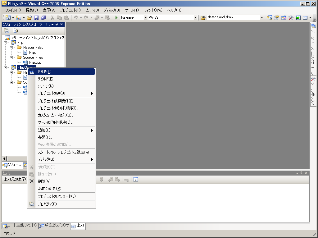
Build the component as in Figure 21.
Test the component
For testing, the Flip component will be connected to the USBCameraAcquireComp and USBCameraMonitorComp sample components supplied with OpenRTM-aist.
Start the name service
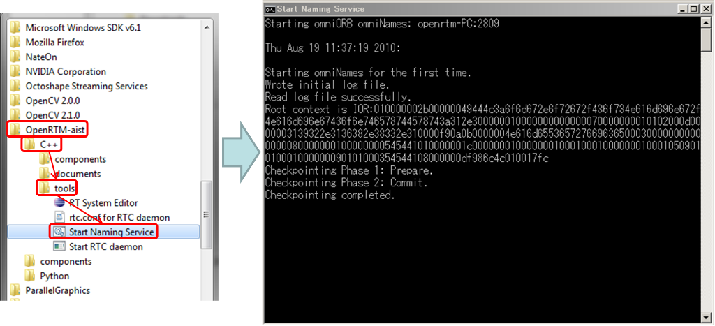
The omniORB name service must be started. From the Start menu, go to All Programs > OpenRTM-aist > C++ > examples > Start Naming Service.
Write rtc.conf
The rtc.conf file is used to tell an RT-Component such parameters as the address of the name server, the format to use when registering with the name server, etc. Copy the following lines into a file called "rtc.conf" and place that file in Flip\FlipComp\Debug or Flip\FlipComp\Release.
 corba.nameservers: localhost
 naming.formats: %n.rtc
Start the Flip component
In the same folder that the rtc.conf file was placed, execute FlipComp.exe.
Start the USBCameraAqcuire and USBCameraMonitor components
The USBCameraAcquire component provides image data captured from a USB camera over its OutPort. The USBCameraMonitor component displays image data received over its InPort. Start them by selecting the following options from the Start menu:
Start > All Programs > OpenRTM-aist > C++ > examples > USBCameraAcquireComp / USBCameraMonitorCpomp
Connect the components
Using RTSystemEditor, connect the three components as in Figure 22.
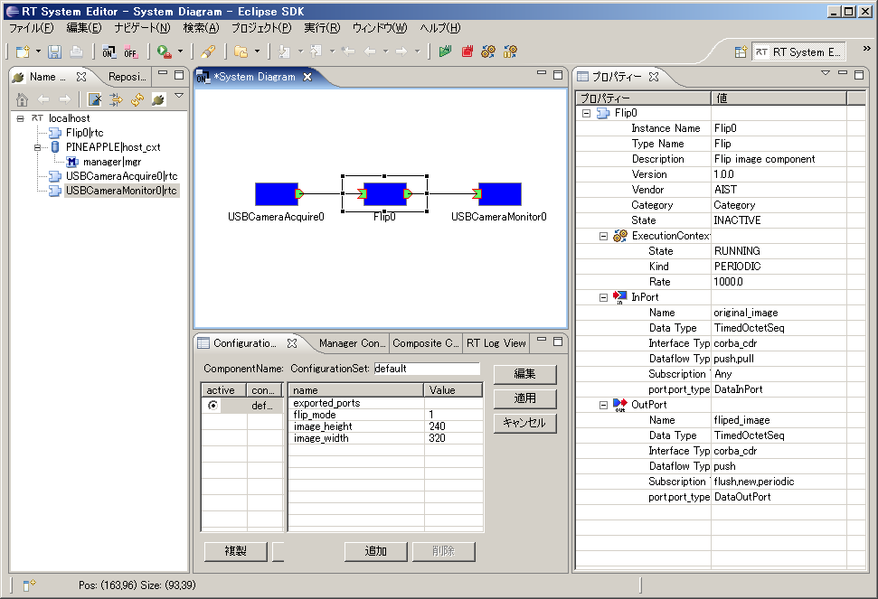
Changing the Flip component configuration parameters
The Flip component's configuration parameters can be changed as in Figure 23. For example, when using the Elecom UCAM-DLM 130HWH USB camera, set image_height and image_width as below.
 image_height : 480
 image_width  : 640
Do the same for the USBCameraMonitor component.
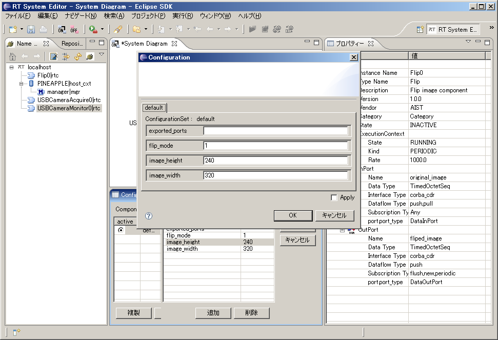
Activate the components
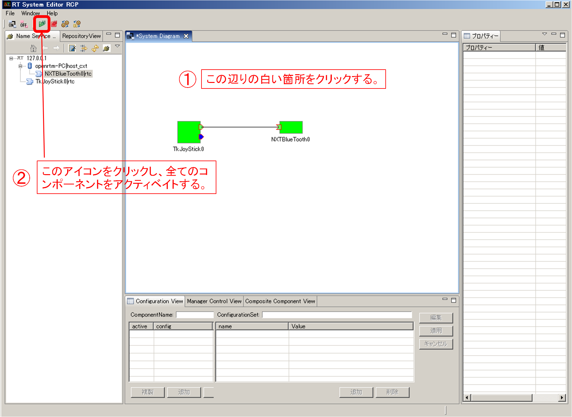
Click the "All" icon in the toolbar for RTSystemEditor. All the components will be activated. If all components started succesfully, RTSystemEditor should resemble Figure 24.
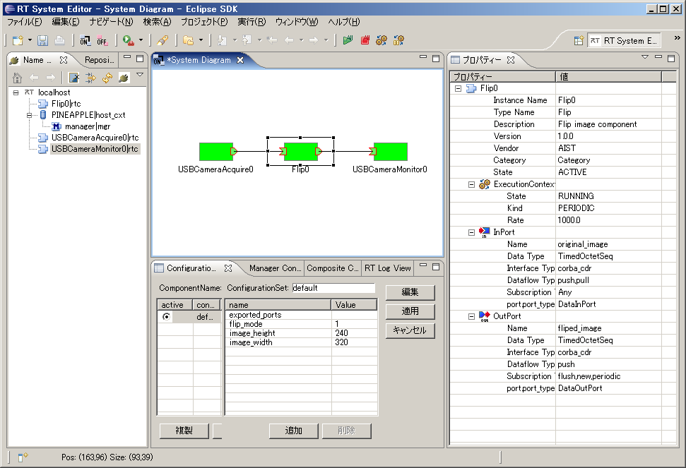
Test
Try changing the Flip component's "flip_mode" configuration parameter to different values of -1, 0 and 1. The displayed image should change accordingly.
Flip component source file
 // -*- C++ -*-
 /*!
  * @file  Flip.cpp
  * @brief Flip image component
  * @date $Date$
  *
  * $Id$
  */

 #include "Flip.h"

 // Module specification
 static const char* flip_spec[] =
   {
     "implementation_id", "Flip",
     "type_name",         "Flip",
     "description",       "Flip image component",
     "version",           "1.0.0",
     "vendor",            "AIST",
     "category",          "Category",
     "activity_type",     "PERIODIC",
     "kind",              "DataFlowComponent",
     "max_instance",      "1",
     "language",          "C++",
     "lang_type",         "compile",
     "exec_cxt.periodic.rate", "1.0",
     // Configuration variables
     "conf.default.flip_mode", "1",
     "conf.default.image_height", "240",
     "conf.default.image_width", "320",
     ""
   };

 /*!
  * @brief constructor
  * @param manager Maneger Object
  */
 Flip::Flip(RTC::Manager* manager)
   : RTC::DataFlowComponentBase(manager),
     m_image_origIn("original_image", m_image_orig),
     m_image_flipOut("fliped_image", m_image_flip),
     dummy(0),
     m_image_buff(0),
     m_flip_image_buff(0)
 {
   // Registration: InPort/OutPort/Service

   // Set InPort buffers
   registerInPort("original_image", m_image_origIn);

   // Set OutPort buffer
   registerOutPort("fliped_image", m_image_flipOut);
 }

 /*!
  * @brief destructor
  */
 Flip::~Flip()
 {
 }


 RTC::ReturnCode_t Flip::onInitialize()
 {
   // Bind variables and configuration variable
   bindParameter("flip_mode", m_flip_mode, "1");
   bindParameter("image_height", m_img_height, "240");
   bindParameter("image_width", m_img_width, "320");
   return RTC::RTC_OK;
 }

 RTC::ReturnCode_t Flip::onActivated(RTC::UniqueId ec_id)
 {
   // Image memory store allocation
   m_image_buff = cvCreateImage(cvSize(m_img_width, m_img_height), IPL_DEPTH_8U, 3);
   m_flip_image_buff = cvCreateImage(cvSize(m_img_width, m_img_height), IPL_DEPTH_8U, 3);
   return RTC::RTC_OK;
 }


 RTC::ReturnCode_t Flip::onDeactivated(RTC::UniqueId ec_id)
 {
   // Image memory store deallocation
   cvReleaseImage(&m_image_buff);
   cvReleaseImage(&m_flip_image_buff);
   return RTC::RTC_OK;
 }


 RTC::ReturnCode_t Flip::onExecute(RTC::UniqueId ec_id)
 {
   // Check for new data
   if (m_image_origIn.isNew()) {
     // Read data from the InPort
     m_image_origIn.read();

     // Copy the image data from the InPort to IplImage.imageData
     memcpy(m_image_buff->imageData,(void *)&(m_image_orig.data[0]),m_image_orig.data.length());

     // Flip the image data. m_flip_mode 0: flip on X, 1: flip on Y, -1: flip on both
     cvFlip(m_image_buff, m_flip_image_buff, m_flip_mode);

     // Get the image data size
     int len = m_flip_image_buff->nChannels * m_flip_image_buff->width * m_flip_image_buff->height;
     m_image_flip.data.length(len);

     // Copy the flipped image data to the OutPort
     memcpy((void *)&(m_image_flip.data[0]),m_flip_image_buff->imageData,len);

     // Output the image data
     m_image_flipOut.write();
   }
   return RTC::RTC_OK;
 }

 extern "C"
 {

   void FlipInit(RTC::Manager* manager)
   {
     RTC::Properties profile(flip_spec);
     manager->registerFactory(profile,
                              RTC::Create<Flip>,
                              RTC::Delete<Flip>);
   }

 };
Flip component header file
 // -*- C++ -*-
 /*!
  * @file  Flip.h
  * @brief Flip image component
  * @date  $Date$
  *
  * $Id$
  */

 #ifndef FLIP_H
 #define FLIP_H

 #include <rtm/Manager.h>
 #include <rtm/DataFlowComponentBase.h>
 #include <rtm/CorbaPort.h>
 #include <rtm/DataInPort.h>
 #include <rtm/DataOutPort.h>
 #include <rtm/idl/BasicDataTypeSkel.h>

 // (1)  Include the OpenCV headers
 #include<cv.h>
 #include<cxcore.h>
 #include<highgui.h>


 using namespace RTC;

 /*!
  * @class Flip
  * @brief Flip image component
  *
  */
 class Flip
   : public RTC::DataFlowComponentBase
 {
  public:
   /*!
    * @brief constructor
    * @param manager Maneger Object
    */
   Flip(RTC::Manager* manager);

   /*!
    * @brief destructor
    */
   ~Flip();


   /*!
    *
    * The initialize action (on CREATED->ALIVE transition)
    * formaer rtc_init_entry()
    *
    * @return RTC::ReturnCode_t
    *
    *
    */
    virtual RTC::ReturnCode_t onInitialize();

   /***
    *
    * The activated action (Active state entry action)
    * former rtc_active_entry()
    *
    * @param ec_id target ExecutionContext Id
    *
    * @return RTC::ReturnCode_t
    *
    *
    */
   virtual RTC::ReturnCode_t onActivated(RTC::UniqueId ec_id);

   /***
    *
    * The deactivated action (Active state exit action)
    * former rtc_active_exit()
    *
    * @param ec_id target ExecutionContext Id
    *
    * @return RTC::ReturnCode_t
    *
    *
    */
   virtual RTC::ReturnCode_t onDeactivated(RTC::UniqueId ec_id);

   /***
    *
    * The execution action that is invoked periodically
    * former rtc_active_do()
    *
    * @param ec_id target ExecutionContext Id
    *
    * @return RTC::ReturnCode_t
    *
    *
    */
   virtual RTC::ReturnCode_t onExecute(RTC::UniqueId ec_id);


  protected:
   // Configuration variable declaration
   /*!
    * flip_mode = 0: flipping around x-axis
    * flip_mode > 1: flipping around y-axis
    * flip_mode < 0: flipping around both axises
    * - Name: flip_mode flip_mode
    * - DefaultValue: 1
    */
   int m_flip_mode;
   /*!
    *
    * - Name:  m_img_height
    * - DefaultValue: 240
    * - Image height
    */
   int m_img_height;
   /*!
    *
    * - Name:  m_img_width
    * - DefaultValue: 320
    * - Image width
    */
   int m_img_width;


   // DataInPort declaration
   TimedOctetSeq m_image_orig;
   InPort<TimedOctetSeq> m_image_origIn;


   // DataOutPort declaration
   TimedOctetSeq m_image_flip;
   OutPort<TimedOctetSeq> m_image_flipOut;

  private:
   int dummy;
   IplImage* m_image_buff;
   IplImage* m_flip_image_buff;
 };


 extern "C"
 {
   void FlipInit(RTC::Manager* manager);
 };

 #endif // FLIP_H
Flip component prebuilt package
A prebuilt package of the component can be downloaded from here. Remove the underscore from the name and decompress the file.
Development of RTC (OpenCV: use of the type CameraImage )
- はじめに
- OpenCV ライブリの RTコンポーネント化 (Flipコンポーネント)
はじめに
ここでは、OpenCV ライブラリを VC9 にて RTコンポーネント化する手順を紹介します。
OpenCV とは
OpenCV とはインテルが開発・公開しているオープンソースのコンピュータービジョン向けライブラリです。
Wikipedia より抜粋。
作成する RTコンポーネント
- Flip コンポーネント: OpenCV ライブラリのうち、cvFlip() 関数を用いて画像の反転を行う RTコンポーネント。
OpenCV ライブリの RTコンポーネント化 (Flipコンポーネント)
ここでは、OpenCV ライブラリのうち、画像の反転を行う cvFlip() を VC9 にて RTコンポーネント化します。
以下は、作業の流れです。
- cvFlip 関数について
- コンポーネントの概要
- 動作環境・開発環境
- Flip コンポーネントの雛型の生成
- アクティビティ処理の実装
- コンポーネントの動作確認
cvFlip 関数について
cvFlip 関数は、2次元配列を垂直、水平、または両軸で反転します。
 void cvFlip(IplImage* src, IplImage* dst=NULL, int flip_mode=0);
 #define cvMirror cvFlip

 src       入力配列
 dst       出力配列。もし dst = NULL であれば、src が上書きされます。
 flip_mode 配列の反転方法の指定内容:
  flip_mode = 0: X軸周りでの反転(上下反転)
  flip_mode > 0: Y軸周りでの反転(左右反転)
  flip_mode < 0: 両軸周りでの反転(上下左右反転)
コンポーネントの概要
InPort からの入力画像を反転し OutPort から出力するコンポーネント。
反転の対象軸は、RTC のコンフィギュレーション機能を使用して flipMode という名前のパラメーターで指定します。
flipMode は、反転したい方向に応じて下記のように指定してください。
- 上下反転したい場合、0
- 左右反転したい場合、1
- 上下左右反転したい場合、-1
作成する RTC の仕様は以下のとおりです。
- InPort
- キャプチャーされた画像データ (CameraImage)
- OutPort
- 反転した画像データ (CameraImage)
- Configuration
- 反転方法の指定 (int)
※ CameraImage型は、OpenRTM-aist の InterfaceDataTypes.idl にて下記のように定義されているデータ型です。
   struct CameraImage
     {
         /// Time stamp.
         Time tm;
         /// Image pixel width.
         unsigned short width;
         /// Image pixel height.
         unsigned short height;
         /// Bits per pixel.
         unsigned short bpp;
         /// Image format (e.g. bitmap, jpeg, etc.).
         string format;
         /// Scale factor for images, such as disparity maps,
         /// where the integer pixel value should be divided
         /// by this factor to get the real pixel value.
         double fDiv;
         /// Raw pixel data.
         sequence<octet> pixels;
     };
図1は、それぞれの flipMode での画像処理のイメージ図です。

動作環境・開発環境
- OS: Windows XP SP3
- コンパイラ: Visual C++ 2008 Express Edition 日本語版
- RTSystemEditor 1.0
- RTCBuilder 1.0
Flip コンポーネントの雛型の生成
Flip コンポーネントの雛型の生成は、RTCBuilder を用いて行います。
RTCBuilder の起動
新規ワークスペースを指定して Eclipse を起動すると、以下のような「ようこそ」画面が表示されます。

この「ようこそ」画面左上の「X」をクリックして画面を閉じると、以下の画面が表示されます。 右上の [Open Perspective] ボタンをクリックし、プルダウンの「Other…」を選択します。

「RTC Builder」を選択し、[OK] ボタンをクリックします。

RTCBuilder が起動します。
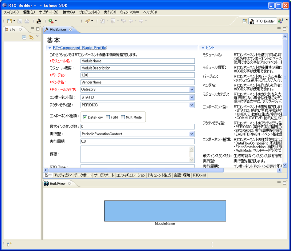
RTCBuilder用 プロジェクトの作成
まず最初に,RT コンポーネントを作成するための Eclipse プロジェクトを作成します。 画面上部のメニューから [ファイル] > [新規] > [プロジェクト] を選択します。

表示された「新規プロジェクト」画面において、[その他] > [RTC ビルダ] を選択し、[次へ] をクリックします。

「プロジェクト名」欄に作成するプロジェクト名を入力して [完了] をクリックします。
指定した名称のプロジェクトが生成され、パッケージエクスプローラー内に追加されます。
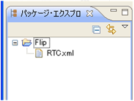
生成したプロジェクト内には、デフォルト値が設定された RTC プロファイル XML(RTC.xml) が自動的に生成されます。
RTC プロファイルエディタの起動
RTC プロファイルエディタを開くには、ツールバーの「 [Open New RtcBuilder Editor] ボタンをクリックするか、メニューから [ファイル] > [Open New Builder Editor] を選択します。

コンポーネントのプロファイル情報入力とコードの生成
1. 「基本」タブを選択し、基本情報を入力します。
-モジュール名: Flip
- モジュール概要: Flip image component
- バージョン: 1.0.0
- ベンダ名: AIST
- モジュールカテゴリ: Category
- コンポーネント型: STATIC
- アクティビティ型: PERIODIC
- コンポーネント種類: DataFlowComponent
- 最大インスタンス数: 1
- 実行型: PeriodicExecutionContext
- 実行周期: 0.0 (図13では1.0となってますが,0.0として下さい.)
-Output Project: Flip
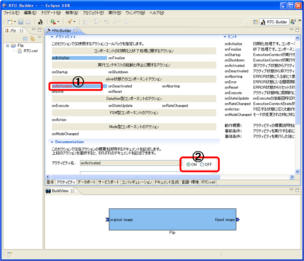
2. 「アクティビティ」タブを選択し、使用するアクションコールバックを指定します。
Flip コンポーネントでは、onActivated()、onDeactivated()、onExecute()コ ールバックを使用します。 図14のように①の onAtivated をクリック後に ②のラジオボタンの [ON] にチェックを入れます。onDeactivated、onExecute についても同様の操作を行います。
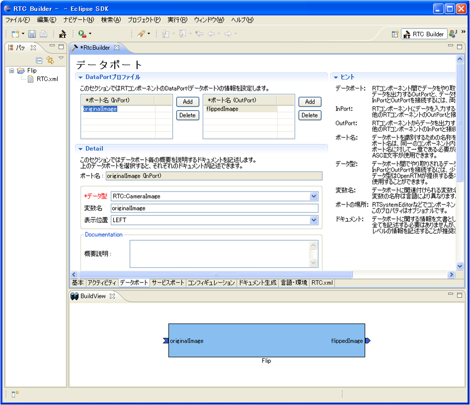
3. 「データポート」タブを選択し、データポートの情報を入力します。
-InPort Profile:
- ポート名: originalImage
- データ型: CameraImage
- 変数名: originalImage
- 表示位置: left
-OutPort Profile: - ポート名: flippedImage
- データ型: CameraImage
- 変数名: flippedImage
- 表示位置: right
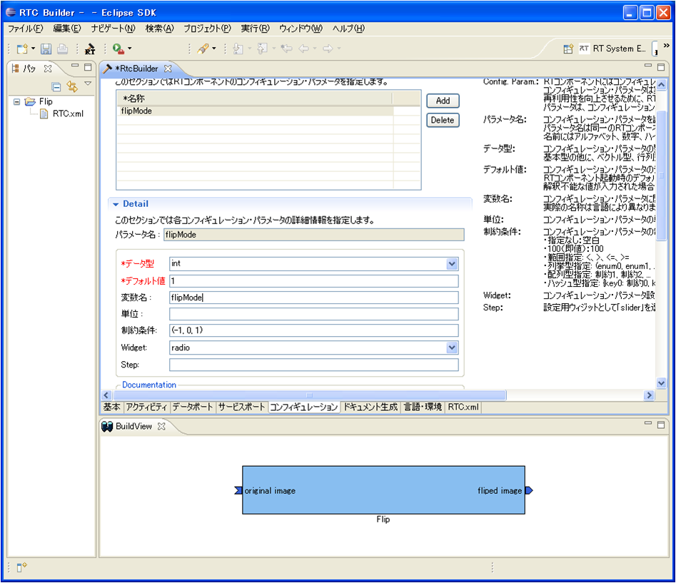
4. 「コンフィギュレーション」タブを選択し、Configuration の情報を入力します。
ラジオボタンでコンフィギュレーションの変更を行います。
-flipMode
- 名称: flipMode
- データ型: int
- デフォルト値: 1
- 変数名: flipMode
- 制約条件: (-1, 0, 1) ※ (-1: 上下左右反転, 0: 上下反転, 1: 左右反転)
- Widget: radio
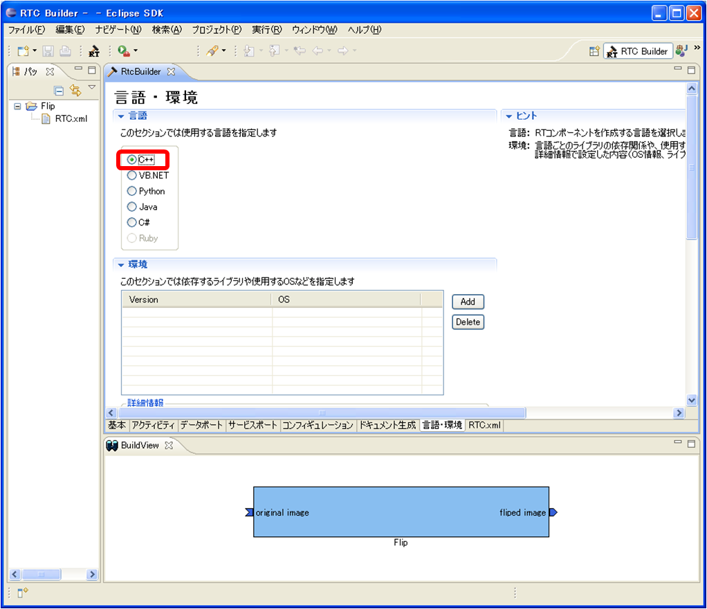
5. 「言語・環境」タブを選択し、プログラミング言語を選択します。
今回は、C++(言語)を選択します。
6. 「基本」タブにある [コード生成] ボタンをクリックし、コンポーネントの雛型を生成します。
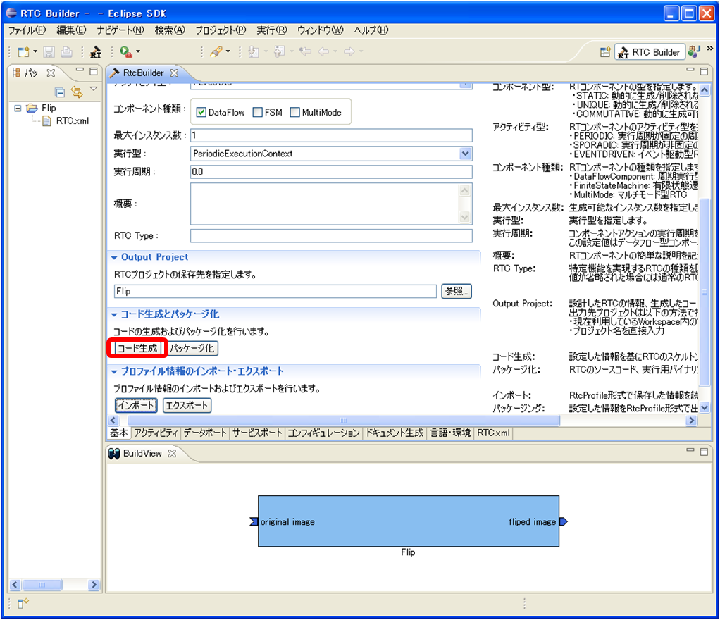
※ 生成されるコード群は、Eclipse 起動時に指定したワークスペースフォルダーの中に生成されます。現在のワークスペースは、[ファイル] > [ワークスペースの切り替え] で確認することができます。
アクティビティ処理の実装
Flip コンポーネントでは、InPort から受け取った画像を画像保存用バッファに保存し、その保存した画像を OpenCV の cvFlip() 関数にて変換します。その後、変換された画像を OutPort から送信します。
onActivated()、onExecute()、onDeactivated() での処理内容を図19に示します。

onExecute() での処理を図20に示します。

OpenCV用 ユーザープロパティシートのコピー
プロパティシートとは、コンパイルに必要な種々のオプション(インクルードパス、ライブラリロードバス、ライブラリ)やマクロを記述した VC の設定ファイルの一種です。 RTCBuilder や rtc-template で生成した VC用のプロジェクトでは、VC のプロパティシートを使用して各種オプションを与えています。また、ユーザーが追加でオプションを追加できるように、ユーザー定義のプロパティシートもインクルードするようになっています。- rtm_config.vsprop:OpenRTM に関する情報を含むプロパティシート。インストールされている OpenRTM-aist に依存するファイルであるため、copyprops.bat を使用して OpenRTM のシステムディレクトリーからカレントのプロジェクトへコピーします。
- user_config.vsprops:ユーザー定義のプロパティシート。デフォルトは空です。使い方は、ソースコード:OpenRTM-aist/win32/OpenRTM-aist/example/USBCamera の中に入っているuser_config.vsprops (OpenCV用の設定)を参考にしてください。
以下の内容を user_config.vsprops というファイル名で保存し、Flip フォルダーにコピーしてください。
もしくは、下記より vsprops ファイルをダウンロードし、Flip フォルダーに保存してください。
※ 既に Flip フォルダーには user_config.vsprops ファイルが存在していますが、上書きして構いません。
<?xml version="1.0" encoding="shift_jis"?>
<VisualStudioPropertySheet
ProjectType="Visual C++"
Version="8.00"
Name="OpenCV21"
>
<Tool
Name="VCCLCompilerTool"
AdditionalIncludeDirectories="$(cv_includes)"
/>
<Tool
Name="VCLinkerTool"
AdditionalLibraryDirectories="$(cv_libdir)"
/>
<UserMacro
Name="user_lib"
Value="$(cv_lib)"
/>
<UserMacro
Name="user_libd"
Value="$(cv_libd)"
/>
<UserMacro
Name="cv_root"
Value="C:\OpenCV2.1"
/>
<UserMacro
Name="cv_includes"
Value=""$(cv_root)\include\opencv""
/>
<UserMacro
Name="cv_libdir"
Value=""$(cv_root)\lib""
/>
<UserMacro
Name="cv_bin"
Value="$(cv_root)\bin"
/>
<UserMacro
Name="cv_lib"
Value="cv210.lib cvaux210.lib highgui210.lib cxcore210.lib"
/>
<UserMacro
Name="cv_libd"
Value="cv210d.lib cvaux210d.lib highgui210d.lib cxcore210d.lib"
/>
</VisualStudioPropertySheet>copyprops.bat の実行
copyprops.batというファイルを実行することで、rtm_config.vspropsというファイルがコピーされます。
rtm_config.vspropsファイルは、RTコンポーネントをVC++でビルドするために必要なインクルードパスやリンクするライブラリ等が記述されたファイルです。
ヘッダファイルの編集
- OpenCV のライブラリを使用するため、OpenCV のインクルードファイルをインクルードします。
 //OpenCV 用インクルードファイルのインクルード
 #include<cv.h>
 #include<cxcore.h>
 #include<highgui.h>
- この cvFlip コンポーネントでは、画像領域の確保、Flip 処理、確保した画像領域の解放のそれぞれの処理を行います。これらの処理は、それぞれ onActivated()、onDeactivated()、onExecute() のコールバック関数にて行います。
   /***
    *
    * The activated action (Active state entry action)
    * former rtc_active_entry()
    *
    * @param ec_id target ExecutionContext Id
    *
    * @return RTC::ReturnCode_t
    *
    *
    */
   virtual RTC::ReturnCode_t onActivated(RTC::UniqueId ec_id);

   /***
    *
    * The deactivated action (Active state exit action)
    * former rtc_active_exit()
    *
    * @param ec_id target ExecutionContext Id
    *
    * @return RTC::ReturnCode_t
    *
    *
    */
   virtual RTC::ReturnCode_t onDeactivated(RTC::UniqueId ec_id);

   /***
    *
    * The execution action that is invoked periodically
    * former rtc_active_do()
    *
    * @param ec_id target ExecutionContext Id
    *
    * @return RTC::ReturnCode_t
    *
    *
    */
virtual RTC::ReturnCode_t onExecute(RTC::UniqueId ec_id);- 反転した画像の保存用にメンバー変数を追加します。
   IplImage* m_imageBuff;
   IplImage* m_flipImageBuff;
ソースファイルの編集
下記のように、onActivated()、onDeactivated()、onExecute() を実装します。
 RTC::ReturnCode_t Flip::onActivated(RTC::UniqueId ec_id)
 {
   // イメージ用メモリーの初期化
   m_imageBuff = NULL;
   m_flipImageBuff = NULL;

   // OutPort の画面サイズの初期化
   m_flippedImage.width = 0;
   m_flippedImage.height = 0;

   return RTC::RTC_OK;
 }


 RTC::ReturnCode_t Flip::onDeactivated(RTC::UniqueId ec_id)
 {
   if(m_imageBuff != NULL)
   {
     // イメージ用メモリーの解放
     cvReleaseImage(&m_imageBuff);
     cvReleaseImage(&m_flipImageBuff);
   }

   return RTC::RTC_OK;
 }


 RTC::ReturnCode_t Flip::onExecute(RTC::UniqueId ec_id)
 {
   // 新しいデータのチェック
   if (m_originalImageIn.isNew()) {
     // InPort データの読み込み
     m_originalImageIn.read();

     // InPort と OutPort の画面サイズ処理およびイメージ用メモリーの確保
     if( m_originalImage.width != m_flippedImage.width || m_originalImage.height != m_flippedImage.height)
       {
     m_flippedImage.width = m_originalImage.width;
     m_flippedImage.height = m_originalImage.height;

     // InPort のイメージサイズが変更された場合
     if(m_imageBuff != NULL)
       {
         cvReleaseImage(&m_imageBuff);
         cvReleaseImage(&m_flipImageBuff);
       }

     // イメージ用メモリーの確保
     m_imageBuff = cvCreateImage(cvSize(m_originalImage.width, m_originalImage.height), IPL_DEPTH_8U, 3);
     m_flipImageBuff = cvCreateImage(cvSize(m_originalImage.width, m_originalImage.height), IPL_DEPTH_8U, 3);
       }

     // InPort の画像データを IplImage の imageData にコピー
     memcpy(m_imageBuff->imageData,(void *)&(m_originalImage.pixels[0]),m_originalImage.pixels.length());

     // InPort からの画像データを反転する。 m_flipMode 0: X軸周り, 1: Y軸周り, -1: 両方の軸周り
     cvFlip(m_imageBuff, m_flipImageBuff, m_flipMode);

     // 画像データのサイズ取得
     int len = m_flipImageBuff->nChannels * m_flipImageBuff->width * m_flipImageBuff->height;
     m_flippedImage.pixels.length(len);

     // 反転した画像データを OutPort にコピー
     memcpy((void *)&(m_flippedImage.pixels[0]),m_flipImageBuff->imageData,len);

     // 反転した画像データを OutPort から出力する。
     m_flippedImageOut.write();
   }

   return RTC::RTC_OK;
 }
ビルドの実行
Flip_vc9.sln ファイルをダブルクリックし、Visual C++ 2008 を起動します。
Visual C++ 2008 の起動後、図21のようにし、コンポーネントのビルドを行います。

Flip コンポーネントの動作確認
ここでは、「OpenCV用RTC群 (Win32用インストーラ)」にてインストールした USBCameraAqcuireComp コンポーネントと、USBCameraMonitorCom コンポーネント、それと、今回作成した Flip コンポーネントを接続し動作確認を行います。
NameService の起動
omniORB のネームサービスを起動します。
[スタート] > [すべてのプログラム] > [OpenRTM-aist] > [C++] > [tools] の順に辿り、「Start Naming Service」をクリックしてください。
&color(RED){※ 「Star Naming Service」をクリックしても omniNames が起動されない場合は、フルコンピューター名が14文字以内に設定されているかを確認してください。
rtc.confの作成
RTコンポーネントでは、ネームサーバーのアドレスやネームサーバーへの登録フォーマットなどの情報を rtc.conf というファイルで指定する必要があります。
下記の内容を rtc.conf というファイル名で保存し、Flip\FlipComp\Debug(もしくは、Release)フォルダーに置いて下さい。
※ Eclipse 起動時に workspace をデフォルトのままにしていた場合、Flip フォルダーのパスは、
C:\Documents and Settings\<ログインユーザー名>\workspace となります。
 corba.nameservers: localhost
 naming.formats: %n.rtc
Flip コンポーネントの起動
Flip コンポーネントを起動します。
先程 rtc.conf ファイルを置いたフォルダーにある、FlipComp.exe ファイルを実行して下さい。
USBCameraAqcuire、USBCameraMonitor コンポーネントの起動
USB カメラのキャプチャ画像を OutPort から出力する USBCameraAqcuireComp コンポーネントと、InPort で受け取った画像を画面に表示する USBCameraMonitorComp コンポーネントを起動します。
これら2つのコンポーネントは、下記の手順にて起動できます。
[スタート] > [すべてのプログラム] > [OpenRTM-aist] > [components] > [C++] > [OpenCV] を選択し、「USBCameraAqcuireComp」と「USBCameraMonitorComp」をそれぞれクリックして実行します。
コンポーネントの接続
図22のように、RTSystemEditor にて USBCameraAqcuireComp、Flip、USBCameraMonitorComp コンポーネントを接続します。
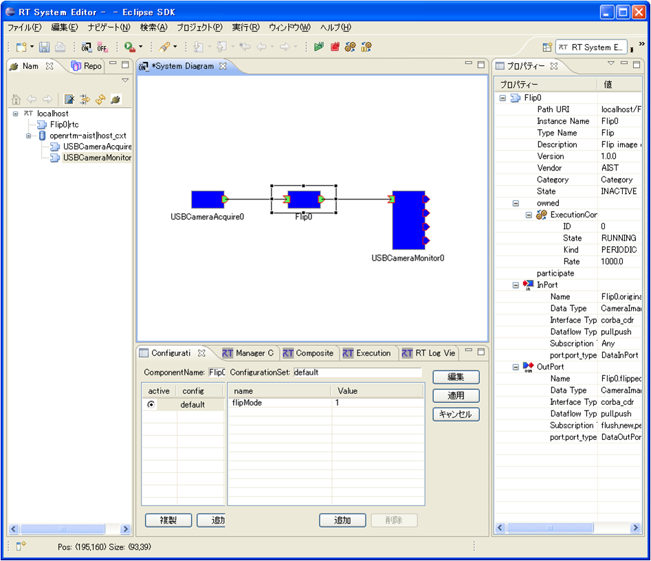
コンポーネントの Activate
RTSystemEditor の上部にあります「ALL」というアイコンをクリックし、全てのコンポーネントをアクティベートします。
正常にアクティベートされた場合、図23のように黄緑色でコンポーネントが表示されます。
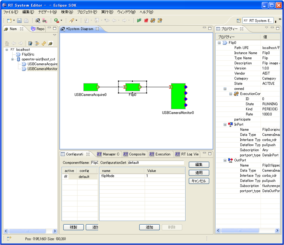
動作確認
図24のようにコンフィギュレーションビューにてコンフィギュレーションを変更することができます。
Flip コンポーネントのコンフィギュレーションパラメーター「flipMode」を「0」や「-1」などに変更し、画像の反転が行われるかを確認してください。
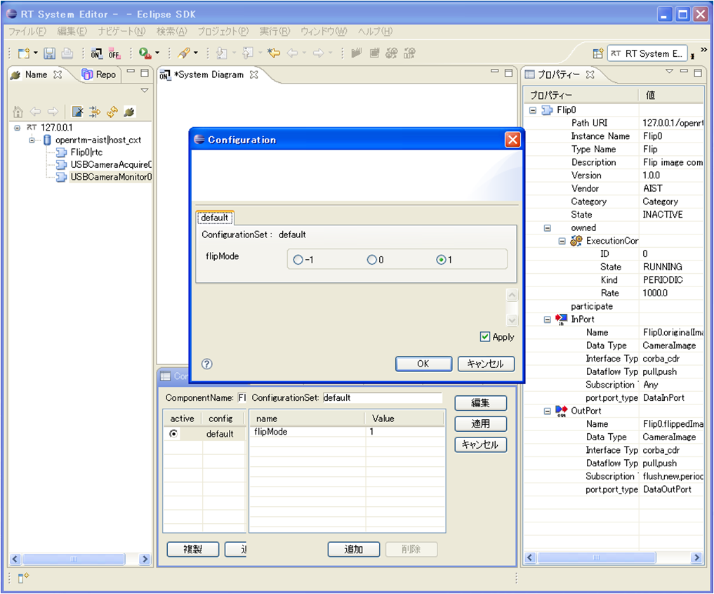
Flip コンポーネントのソースファイル
 // -*- C++ -*-
 /*!
  * @file  Flip.cpp
  * @brief Flip image component
  * @date $Date$
  *
  * $Id$
  */

 #include "Flip.h"

 // Module specification
 static const char* flip_spec[] =
   {
     "implementation_id", "Flip",
     "type_name",         "Flip",
     "description",       "Flip image component",
     "version",           "1.0.0",
     "vendor",            "AIST",
     "category",          "Category",
     "activity_type",     "PERIODIC",
     "kind",              "DataFlowComponent",
     "max_instance",      "1",
     "language",          "C++",
     "lang_type",         "compile",
     // Configuration variables
     "conf.default.flipMode", "1",
     // Widget
     "conf.__widget__.flipMode", "radio",
     // Constraints
     "conf.__constraints__.flip_mode", "(-1,0,1)",
     ""
   };

 /*!
  * @brief constructor
  * @param manager Maneger Object
  */
 Flip::Flip(RTC::Manager* manager)
   : RTC::DataFlowComponentBase(manager),
     m_originalImageIn("originalImage", m_originalImage),
     m_flippedImageOut("flippedImage", m_flippedImage)
 {
 }

 /*!
  * @brief destructor
  */
 Flip::~Flip()
 {
 }


 RTC::ReturnCode_t Flip::onInitialize()
 {
   // Registration: InPort/OutPort/Service
   // Set InPort buffers
   addInPort("originalImage", m_originalImageIn);

   // Set OutPort buffer
   addOutPort("flippedImage", m_flippedImageOut);

   // Bind variables and configuration variable
   bindParameter("flipMode", m_flipMode, "1");

   return RTC::RTC_OK;
 }


 RTC::ReturnCode_t Flip::onActivated(RTC::UniqueId ec_id)
 {
   // イメージ用メモリーの初期化
   m_imageBuff = NULL;
   m_flipImageBuff = NULL;

   // OutPort の画面サイズの初期化
   m_flippedImage.width = 0;
   m_flippedImage.height = 0;

   return RTC::RTC_OK;
 }


 RTC::ReturnCode_t Flip::onDeactivated(RTC::UniqueId ec_id)
 {
   if(m_imageBuff != NULL)
   {
     // イメージ用メモリーの解放
     cvReleaseImage(&m_imageBuff);
     cvReleaseImage(&m_flipImageBuff);
   }

   return RTC::RTC_OK;
 }


 RTC::ReturnCode_t Flip::onExecute(RTC::UniqueId ec_id)
 {
   // 新しいデータのチェック
   if (m_originalImageIn.isNew()) {
     // InPort データの読み込み
     m_originalImageIn.read();

     // InPort と OutPort の画面サイズ処理およびイメージ用メモリーの確保
     if( m_originalImage.width != m_flippedImage.width || m_originalImage.height != m_flippedImage.height)
       {
     m_flippedImage.width = m_originalImage.width;
     m_flippedImage.height = m_originalImage.height;

     // InPort のイメージサイズが変更された場合
     if(m_imageBuff != NULL)
       {
         cvReleaseImage(&m_imageBuff);
         cvReleaseImage(&m_flipImageBuff);
       }

     // イメージ用メモリーの確保
     m_imageBuff = cvCreateImage(cvSize(m_originalImage.width, m_originalImage.height), IPL_DEPTH_8U, 3);
     m_flipImageBuff = cvCreateImage(cvSize(m_originalImage.width, m_originalImage.height), IPL_DEPTH_8U, 3);
       }

     // InPort の画像データを IplImage の imageData にコピー
     memcpy(m_imageBuff->imageData,(void *)&(m_originalImage.pixels[0]),m_originalImage.pixels.length());

     // InPort からの画像データを反転する。 m_flipMode 0: X軸周り, 1: Y軸周り, -1: 両方の軸周り
     cvFlip(m_imageBuff, m_flipImageBuff, m_flipMode);

     // 画像データのサイズ取得
     int len = m_flipImageBuff->nChannels * m_flipImageBuff->width * m_flipImageBuff->height;
     m_flippedImage.pixels.length(len);

     // 反転した画像データを OutPortにコピー
     memcpy((void *)&(m_flippedImage.pixels[0]),m_flipImageBuff->imageData,len);

     // 反転した画像データを OutPortから出力する。
     m_flippedImageOut.write();
   }

   return RTC::RTC_OK;
 }


 extern "C"
 {

   void FlipInit(RTC::Manager* manager)
   {
     coil::Properties profile(flip_spec);
     manager->registerFactory(profile,
                              RTC::Create<Flip>,
                              RTC::Delete<Flip>);
   }

 };
Flip コンポーネントのヘッダファイル
 // -*- C++ -*-
 /*!
  * @file  Flip.h
  * @brief Flip image component
  * @date  $Date$
  *
  * $Id$
  */

 #ifndef FLIP_H
 #define FLIP_H

 #include <rtm/Manager.h>
 #include <rtm/DataFlowComponentBase.h>
 #include <rtm/CorbaPort.h>
 #include <rtm/DataInPort.h>
 #include <rtm/DataOutPort.h>
 #include <rtm/idl/BasicDataTypeSkel.h>
 #include <rtm/idl/ExtendedDataTypesSkel.h>
 #include <rtm/idl/InterfaceDataTypesSkel.h>

 //OpenCV 用インクルードファイルのインクルード
 #include<cv.h>
 #include<cxcore.h>
 #include<highgui.h>

 using namespace RTC;

 /*!
  * @class Flip
  * @brief Flip image component
  *
  */
 class Flip
   : public RTC::DataFlowComponentBase
 {
  public:
   /*!
    * @brief constructor
    * @param manager Maneger Object
    */
   Flip(RTC::Manager* manager);

   /*!
    * @brief destructor
    */
   ~Flip();

   /***
    *
    * The initialize action (on CREATED->ALIVE transition)
    * formaer rtc_init_entry()
    *
    * @return RTC::ReturnCode_t
    *
    *
    */
    virtual RTC::ReturnCode_t onInitialize();

   /***
    *
    * The activated action (Active state entry action)
    * former rtc_active_entry()
    *
    * @param ec_id target ExecutionContext Id
    *
    * @return RTC::ReturnCode_t
    *
    *
    */
    virtual RTC::ReturnCode_t onActivated(RTC::UniqueId ec_id);

   /***
    *
    * The deactivated action (Active state exit action)
    * former rtc_active_exit()
    *
    * @param ec_id target ExecutionContext Id
    *
    * @return RTC::ReturnCode_t
    *
    *
    */
    virtual RTC::ReturnCode_t onDeactivated(RTC::UniqueId ec_id);

   /***
    *
    * The execution action that is invoked periodically
    * former rtc_active_do()
    *
    * @param ec_id target ExecutionContext Id
    *
    * @return RTC::ReturnCode_t
    *
    *
    */
    virtual RTC::ReturnCode_t onExecute(RTC::UniqueId ec_id);

  protected:
   // Configuration variable declaration
   /*!
    *
    * - Name:  flipMode
    * - DefaultValue: 1
    */
   int m_flipMode;

   // DataInPort declaration
   CameraImage m_originalImage;

   /*!
    */
   InPort<CameraImage> m_originalImageIn;

   // DataOutPort declaration
   CameraImage m_flippedImage;

   /*!
    */
   OutPort<CameraImage> m_flippedImageOut;

  private:
   // 処理画像用バッファ
   IplImage* m_imageBuff;
   IplImage* m_flipImageBuff;
 };


 extern "C"
 {
   DLL_EXPORT void FlipInit(RTC::Manager* manager);
 };

 #endif // FLIP_H
Flip コンポーネントのビルド済みパッケージ
ビルド済みパッケージを下記からダウンロードできます。
拡張子を"zip_"としてますので、"zip"にリネームしてから解凍してください。
Create RT Component (VC++ version)
- RT-Component with DataPorts
RT-Component with DataPorts
Here, how to develop RT-Component(MRCConverter) with DataPort would be shown.
Overview of the RTC
This RTC converts x-y value from input device (ex. joystick) to the wheel velocity of differential drive mobile robot.
The specification of the RTC is the following.
- InPort
- Input values of x-y from joystick (TimedFloatSeq)
- OutPort
- Wheel velocity to the mobile robot (TimedFloatSeq)
Creating template codes of MRCConverter
Here, how to create template codes by using RtcTemplate would be shown.
Creating working folder
Create working directory in any place. In the following, the directory name is MRCConverter.
- Double-click "My Computer"
- Move to working folder
- Create new folder on the target folder
Using rtc-template (CUI version)
Create the following batch file (ex. gen.bat) on the working folder to run the rtc-template easily.
 rtc-template.py -bcxx^
  --module-name=MRCConvertor --module-desc="Convertor component for MobileRobot component"^
  --module-version=1.0.0 --module-vendor=AIST --module-category=Category^
  --module-comp-type=DataFlowComponent --module-act-type=PERIODIC^
  --module-max-inst=1^
  --inport=velFromInput:TimedFloatSeq^
  --outport=velToWheel:TimedFloatSeq
Running rtc-template (with gen.bat)
Run the gen.bat, and the result will be the following.
 >gen.bat
  rtc-template.py -bcxx
  --module-name=MRCConvertor
  --module-desc="Convertor component for MobileRobot component"
  --module-version=1.0.0 --module-vendor=AIST
  --module-category=Category
  --module-comp-type=DataFlowComponent --module-act-type=PERIODIC
  --module-max-inst=1
  --inport=velFromInput:TimedFloatSeq --outport=velToWheel:TimedFloatSeq
   File "MRCConvertor.h" was generated.
   File "MRCConvertor.cpp" was generated.
   File "MRCConvertorComp.cpp" was generated.
   File "Makefile.MRCConvertor" was generated.
   File "MRCConvertorComp_vc8.vcproj" was generated.
   File "MRCConvertor_vc8.vcproj" was generated.
   File "MRCConvertorComp_vc9.vcproj" was generated.
   File "MRCConvertor_vc9.vcproj" was generated.
   File "MRCConvertor_vc8.sln" was generated.
   File "MRCConvertor_vc9.sln" was generated.
   File "copyprops.bat" was generated.
   File "user_config.vsprops" was generated.
   File "README.MRCConvertor" was generated.
   File "MRCConvertor.yaml" was generated.
Some source codes and other files would be generated in the woking diretory.
RtcTemplate on Eclipse (GUI version)
Input the following profiles in the RtcTempalte's editor window.
- Programing language selection: C++
- Module definition
- Module name: MRCConvertor
- Module decription: Convertor component for MobileRobot component
- Module version: 1.0.0
- Module vender: AIST
- Module category: Category
- Component type: DataFlowComponent
- Component's activity type: PERIODIC
- Number of maximum instance: 1
- InPort definition
- Ports: Name:velFromInput Type:TimedFloatSeq
- OutPort definition
- Ports: Name:velToWheel, Type:TimedFloatSeq
After input the component profile, push "Generate" button. Some source codes and other files would be generated in the working folder.
Running copyprops.bat
As the result of the above mentioned operation, copyprops.bat would be generated in the working folder. The copyprops.bat copies rtm_config.vsprops (Visual Studio Property Sheet) from installed OpenRTM-aist folder to current working folder. This file is necessary to build RTC on Visual C++.
Double-click te copyprops.bat.
Implementing MRCConvertor
Launching Visual Studio
Double-click MRCConvertorComp_vc?.sln and launch Visual Studio. XXX_vc8.sln is a solution file for VC2005, XXX_vc9.sln is a solution file for VC2008. Please select an appropriate solution file for your development environment.
Implementing Header File
Open the MRCConverter.h in "MRCConverterComp" -> "Header Files" from Solution Explorer.
- Including other header files
Since this RTC uses STL vector and math library, include these two header files.
 #include <vector>
 // To use Math::M_PI in VC8
 #define _USE_MATH_DEFINES
 #include <math.h>
- Uncomment "virtual RTC::ReturnCode_t onExecute(RTC::UniqueId ec_id);"
- Declaration of member variable and member function
Declare a "convert()" function and its coefficient value "m_k" converting from input value to output wheel velocity.
 private:  float m_k;

  /*!
   * @brief This function converts input data from joystick to velocity of
   *        differential drive mobile robot.
   *        Only m_velFromInput.data[0 and 1] would be used.
   */
  std::vector<float> convert(float x, float y) {
    float th = atan2(y,x);
    float v  = m_k * hypot(x,y);
    std::vector<float> ret_val;
    ret_val.push_back(v * cos(th - (M_PI/4.0))); // left vel
    ret_val.push_back(v * sin(th - (M_PI/4.0))); // right vel
    return ret_val;
  }
Implementing Source File
Open the MRCConverter.cpp in "MRCConverterComp" -> "Source Files" from Solution Explorer.
- Implementing onExecute()
Uncomment "onExecute()" function and implement it as follows.
 /*!
  * @brief This function converts input data from joystick to velocity of
  *        differential drive mobile robot.
  */
 RTC::ReturnCode_t MRCConvertor::onExecute(RTC::UniqueId ec_id)
 {
   if (m_velFromInputIn.isNew()) {
     m_velFromInputIn.read();
     if (m_velFromInput.data.length() > 2) {
       std::vector<float>  con_val = this->convert(m_velFromInput.data[0],m_velFromInput.data[1]);
       for (int i = 0; i < 2; i++)
         m_velToWheel.data[i] = con_val[i];
       m_velToWheelOut.write();
     }
   }
   return RTC::RTC_OK;
 }
This function does the following.
- Checking if a new data is coming by using m_velFromInputIn.isNew() function.
- Reading the data by m_velFromInputIn.read() function, if a new data is coming.
- Converting input data to a velocity of wheels by convert() function.
- Setting converted data to the OutPort variable, and write to OutPort buffer.
Running Build Proces
Click "Build" menu button and build the project.
Creating rtc.conf
Create new file and input the following lines in it. Copy this file to Debug and Release folders.
 corba.nameservers: localhost
 naming.formats: %n.rtc
Running Component
Starting CORBA Name Server
Before running an RT-Component, launch CORBA name server. You can find the name server launching batch file from "Start"->"Program"->"OpenRTM-aist"->"C++"->"Example"->"NameService.bat"
Running MRCConvertorComp.exe
Go to "Debug" or "Release" folder and run MRCConverter.exe.
Development of RT Component (Java version)
- Overview
- Development of RT-Component for Java
- Details on RT-Components for Java
- Others
Overview
OpenRTM-aist Java Overview
OpenRTM-aist is a reference implementation of RT-Middleware which The National Institute of Advanced Industrial Science and Technology - Intelligent Systems Research Institute - Task Intelligence Research Group, has been implementing, distributing, maintaining. The RT-Middleware as well as OpenRTM-aist are the software platforms which divide the various functional components of the robot into the part unit called RT-Component and support the construction of various robotic systems by the integration of various these elements. Currently, in OMG(Object Management Group), these are conformed to the Robotic Technology Component Specification which have been decided.
OpenRTM-aist Java is that OpenRTM-aist for C++ has been ported to Java. OpenRTM-aist Java which has OpenRTM-aist compatible interfaces for C++ enable to use both RT-Component developed using Java and RT-Component developed using C++.
Target
This manual provides procedures for development of RT-Components for Java using OpenRTM-aist Java. This manual targets those who have the basic knowledge of Java.
Prerequisites
Here is a list of environments that are required to run OpenRTM-aist Java.
| Environment | Notes |
| Java Development Kit 5.0 (JDK 5) (http://java.sun.com/products/archive/j2se/5.0_12/index.html ) |
Java1.4 is not supported. |
For more details on the installation procedures, refer to "OpenRTM-aist Java Installation manual. Please check the following before moving on to the development procedures
---The version when running "java -version" matches the version of JDK above (Table1-1).
- Tha path for above JDK installation folder is specified the environment variable JAVA_HOME.
- OpenRTM-aist-0.4.x.jar and commons-cli-1.1.jar are under <JAVA_HOME>\jre\lib\ext\.
- References
- JDK 5 installation instruction Windows,UNIX
- How to set the JAVA_HOME environment variable Windows,UNIX
- Installing OpenRTM-aist-Java-0.4.x Windows,UNIX
- FAQ:"java -version" shows a different version which I have installed.
Development of RT-Component for Java
Here we explain on procedures to develop RT-Components for Java. We will use a component with the following specifications as a sample.
| Basic profile | |
| Component Name | sample |
| Discription | SampleComponent |
| Version | 1.0 |
| Vendor | AIST |
| Category | example |
| Component Type | DataFlowComponent |
| Activity Type | SPORADIC |
| Maximum number of instances | 5 |
| Data InPort | |
| Name | in |
| Type | TimedLong |
| ServiceProvider | |
| IDLPath | IDLs/MyService.idl See Note |
| Port Name | MySvcPort |
| Service Name | myservice0 |
| Service Type | MyService |
| Configuration parameter | |
| Name | multiply |
| Parameter Type | int |
| Default value | 1 |
Note: MyService.idl creates the following IDL file using the appropriate editor. Also, the "IDL Path" in above table is specified to the MyService.idl Path. On Windows, this "IDL Path" must be the full path to MyService.idl.
 typedef sequence<string> EchoList;
 typedef sequence<float> ValueList;
 interface MyService
 {
   string echo(in string msg);
   EchoList get_echo_history();
   void set_value(in float value);
   float get_value();
   ValueList get_value_history();
};The above MyService.idl is the same as the sample one in the folder of Examples/RTMExamples/SimpleService included in OpenRTM-aist-0.4 Java.
Development Procedure of RT-Component with CUI
Generating Skeleton Code with rtc-template
First, you generate the skeleton of RT-Component which you would like to develop using rtc-template. The rtc-templates which have used on CUI as well as GUI are distinguished as rtc-template (for CUI) and RtcTmplate (for GUI). (Otherwise, when rtc-template is described simply, it means that it is used as general term of CUI edition and GUI edition.)
-rtc-template for CUI
When RT-Component which has the following specifications described in Table3-2 is generated using rtc-template for CUI, run this command.
rtc-template -bjava --module-name=Sample --desc= 'Sample Component' --module-version=1.0 --module-vendor=AIST --module-category=example --module-comp-type=DataFlowComponent --module-act-type=SPORADIC --module-max-inst=5 --inport=in:TimedLong --service=MySvcPort:myservice0:MyService --service-idl=IDLs/MyService.idl --config="multiply:int:1"
Note:When rtc-template is executed in the windows environment, you must enclose in double quotation (") such as "Sample component". When enclose in single quotation ('), the options can't work. Also, the line continuous symbols are need to be modified from (\) to (^).
:By this operation, these files are generated in the current directory.|
- Sample.java ・・・・・・・・・・・・・・・・・・・・・・・・・・・・・・・・・・・・・・・・・・・・・・・・・・・・・・・・・・ Classes to define Component Profile, Initialization etc
- Sampleimpl.java ・・・・・・・・・・・・・・・・・・・・・・・・・・・・・・・・・・・・・・・・・・ Main class for a RT-Component
- SampleComp.java ・・・・・・・・・・・・・・・・・・・・・・・・・・・・・・・・・・ Class for launching RT-Component
- MyServiceSVC_impl.java ・・・・・・・・・・・・ Service implementation class
- build_Sample.xml ・・・・・・・・・・・・・・・・・・・・・・・・・・・・・・・・・・・・・・ Build file for the RT-Component
- README.Sample ・・・・・・・・・・・・・・・・・・・・・・・・・・・・・・・・・・・・・・ Read Me file
Building RT-Component which was created
We will imprement the target RT-Component for development based on the skeleton code which was generated with rtc-template. After implementing, buid RT-Component. In OpenRTM-aist Java, the component can be build on both CUI and GUI. In this section, we will explain how to build on CUI.- Build using Apache Ant
RT-Component is built using Apache Ant of the build tool via the console. You can download Apache Ant from the following URL. (For more details on the installation procedures for Apache Ant, refer to it, too.)
http://ant.apache.org/
After installing Apache Ant, move the directory which the build target exists and build it with this command.
> $ANT_HOME$bin\ant -f build_Sample.xml
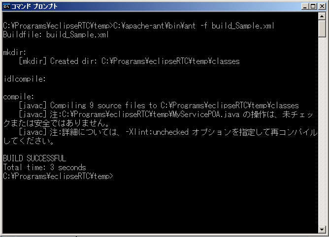
:After the build has completed successfully, the file class will be generated in the directory "classes" under the directory which the build executed. This is the sample screen for the build below.|
Development Procedure of RT-Component with GUI
Collaboration between RtcTemplate and JDT
- Open "New" on Eclipse
It is also possible to develop RT-Component via Project on Eclipse which is Integrated Development Environment. Specify a new workspace and launch Eclipse. (Although you see a "Welcome" screen at that time, close this.)
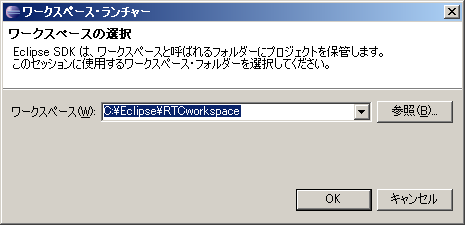 Fig.3-6 Specify a New Workspace
- Create the Java project file
Select [File]-[New]-[Project] in the upper menu bar.
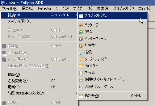 Fig.3-7 Create the project to build (1)
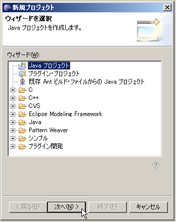
- Select "Java Project" in "New Project" wizard and Press [Next] button.
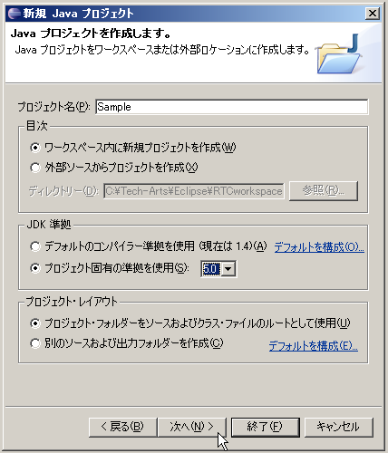
:On the next step of "New Project" wizard, enter "project name" in the dialog box. Check setting of "Compiler compliance level" in "JDK Compliance" is over "5.0" (or over 1.5) and press [Next] button.|
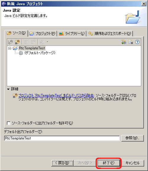
- Set each setting of the creating project in "New Java Project" screen and click on [Finish] button.
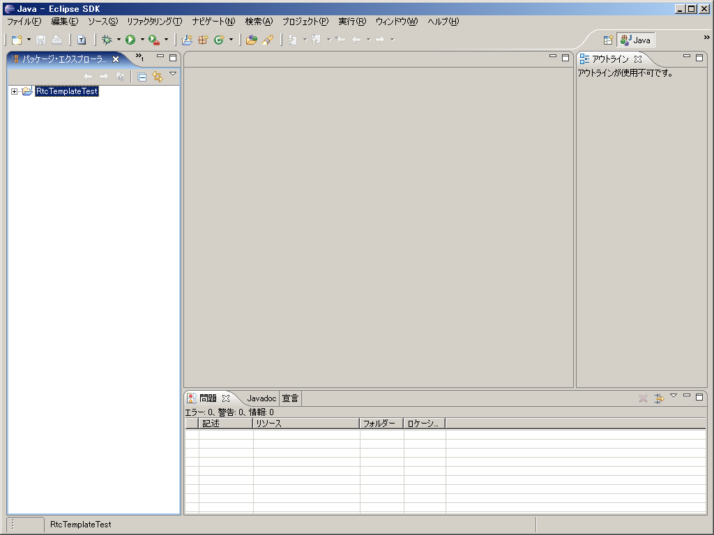
- The specified project is generated and displayed in the "Package Explorer" view.
Note: For more details on the options, setting on Eclipse when creating the project, refer to Eclipse website(http://www.eclipse.org/).
Generating Skeleton Code with RtcTemplate
- Launch of RtcTemplate editor for GUI
Open the editor window of RtcTemplate -> See Launching RtcTemplate directly
Note: please refer RtcTemplate manuals about how to use RtcTemplate and other topics.
- Editing configuration items using RtcTemplate editor
Here is the configurations when you generate skeleton codes for RT-Component which have the specification of Table 3-2, using RtcTemplate for GUI.
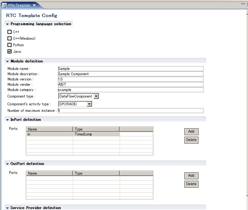
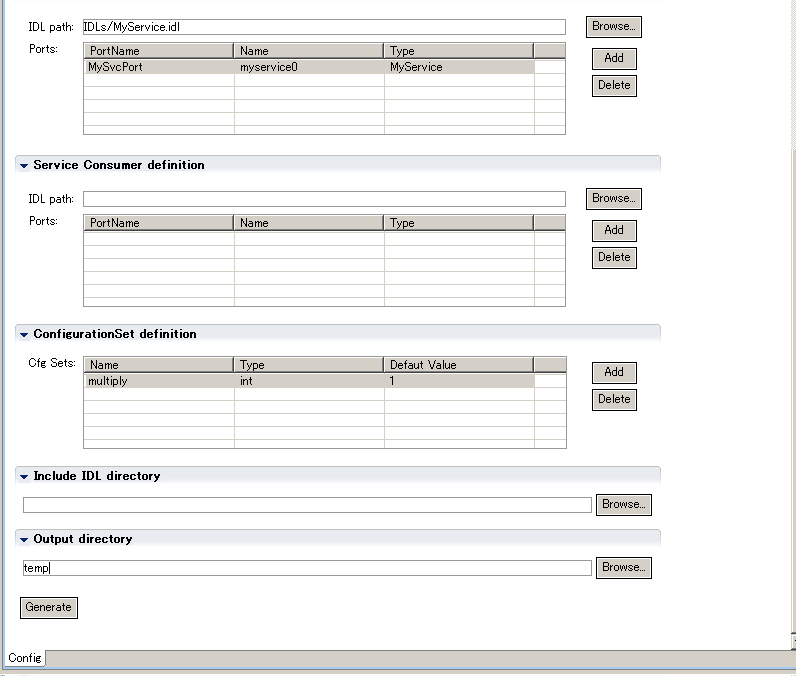 Fig.3-12 Settings of GUI RtcTemplate
:Note:On Windows you must specify a full path for "Output directory", "IDL path:", and so on.|
- Generating codes by [Generate] button
Press [Generate] button to perform code generations. When you generate, make sure to specify the project directory which has been generated before, as "Output directory" field existing bottom of RtcTemplate editor.(Note: "temp" is specified in the figure.)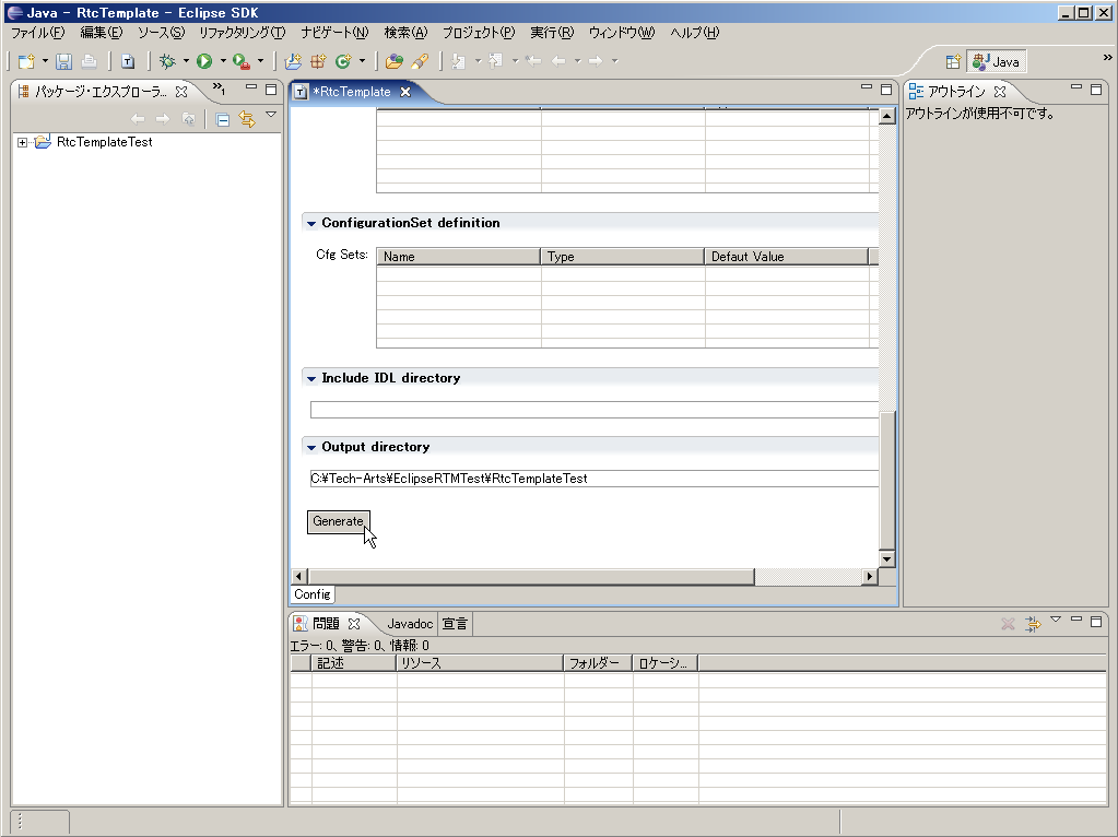 Fig.3-13 Generate Codes
- Adding a variety of generated files to the project
These files are generated in the directory you specified as "Output directory".- Sample.java ・・・・・・・・・・・・・・・・・・・・・・・・・・・・・・・・・・・・・・・・・・・・・・・・・・・・・・・・・・・・・・・・・・・・・・・・・・・・ Class to define Component Profile, initialization process, and so on
- Sampleimpl.java ・・・・・・・・・・・・・・・・・・・・・・・・・・・・・・・・・・・・・・・・・・・・・・・・・・・・・・・・・・・・ Main class for a RT-Component
- SampleComp.java ・・・・・・・・・・・・・・・・・・・・・・・・・・・・・・・・・・・・・・・・・・・・・・・・・・・・ Class to launch the RT-Component
- MyServiceSVC_impl.java ・・・・・・・・・・・・・・・・・・・・・・・・・・・・ Service implementation class
- build_Sample.xml ・・・・・・・・・・・・・・・・・・・・・・・・・・・・・・・・・・・・・・・・・・・・・・・・・・・・・・・・ Build file for the RT-Component
- README.Sample ・・・・・・・・・・・・・・・・・・・・・・・・・・・・・・・・・・・・・・・・・・・・・・・・・・・・・・・・ Read Me file
: By specifying the project directory as "Output directory" field, a variety of generated files are to be added to the project (automatically).|
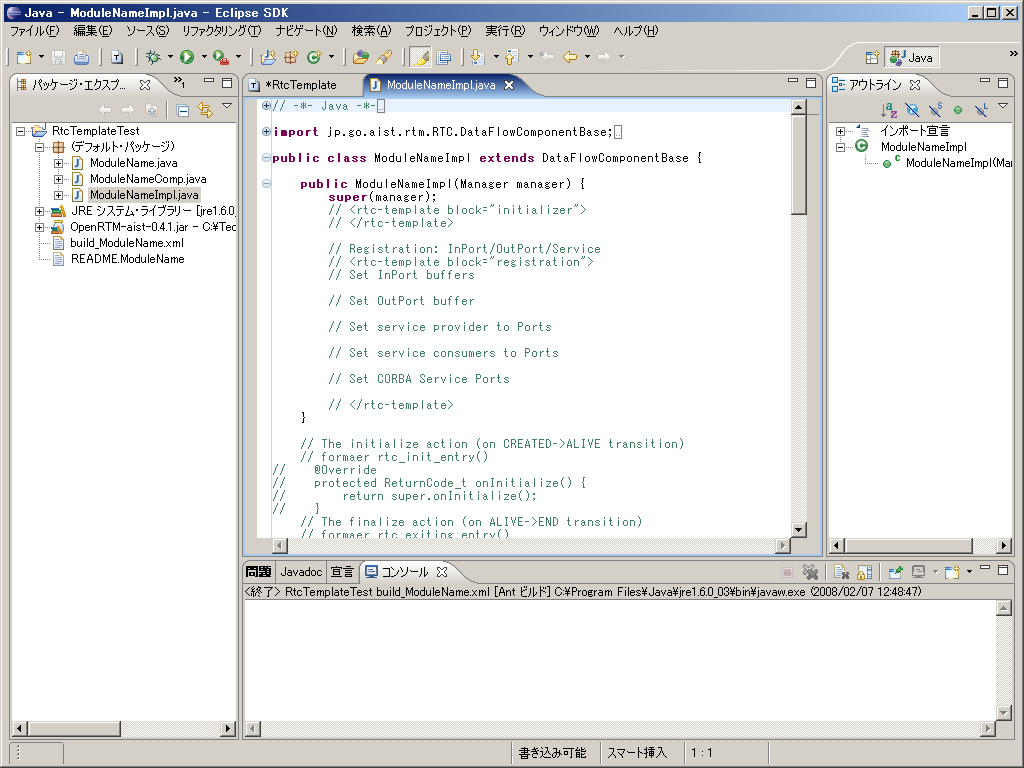
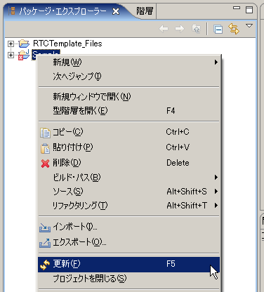
Note In the case of RT-Components which define service ports, errors occur when there are only files generated by Rtctemplate. It is because some of generated files use classes which are generated from IDL files. These required classes will be generated automatically when you build the component.
Note:If OpenRTM-aist Java is not installed on a location which the classpath of the project refers, errors occur, In this case, modify Java Build Path properly of the project, and include the install folder(directory) of OpenRTM-aist Java in the classpath.
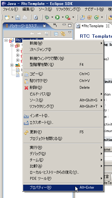
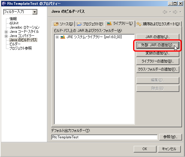
Building RT-Component with Eclipse
- Ant Build
You can build a target RT-Component by right-click build_Sample.xml in Package Explorer, then select [Execute]-[Ant Build].
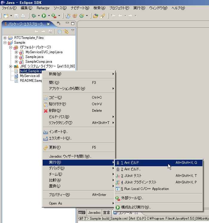 Fig.3-18 Build of the project

- If the build has completed successfully, the class file will be generated in the directory "classes" in project.
Running RT-Component which was created
- Create rtc.conf
Create the file rtc.conf included the following contents in "classes" within the project.corba.nameservers: localhost naming.formats: %n.rtc
rtc.conf
The above rtc.conf is the same as the sample in the folder of "Examples/RTMExamples/SimpleService" included in OpenRTM-aist-0.4 Java.
-Start the Name Server and RtcLink
Double-click start-orbd.bat in the folder "Examples" of samples included in OpenRTM-aist-0.4 Java (Windows), or execute start-orbd.sh (UNIX) to start the Name Server. In addition, launch RtcLink .
- References
- Start Name Server
- Starting RtcLink
-Execution of RT-Component
Open a command prompt or terminal, and set the "classes" directory as current directory. If type likeRT-Component will be shown on RtcLink.> java SampleComp
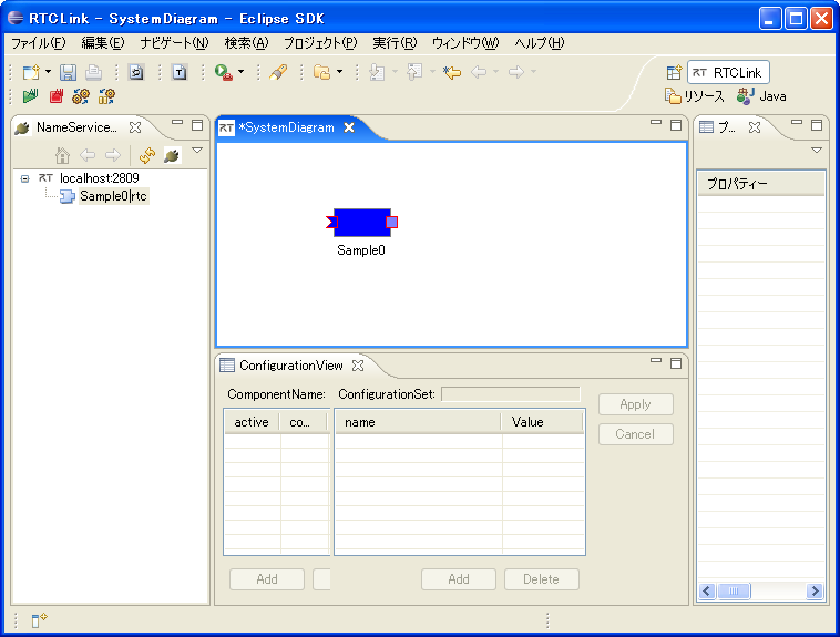 Fig.3-20 State of RtcLink when Sample component succeeds to execute
Details on RT-Components for Java
Structure of RT-Components for Java
The relation between source files of RT-Components for Java, and general functions included in each file is shown in Fig.3-21. For comparison, RT-Components for C++ and RT-Components Java for OpenRTM-aist-0.3 are also shown.
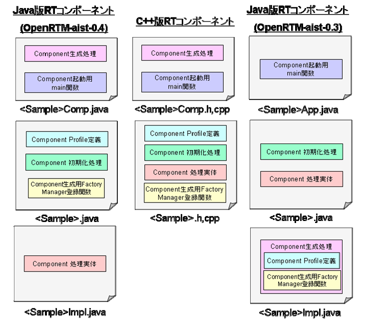
There are these differences between existing RT-Components for C++ and RT-Components for Java.
- Separation of main body of RT-Components functions
In RT-Components for Java, issues about launching and others moved main body of RT-Components functions to XXXImpl classes (In Fig.3-21, <Sample>Impl.java). This makes original RT-Component classes (In Fig.3-21, <Sample>.java) consist of only Component Profile definitions and generating operations to generate a variety of components.
- Changing callback functions to interfaces
Parts defined as callback functions in RT-Components for C++ are interfaces in those for Java.
- ModuleInitProc: Interface for classes to launch components
- RtcNewFunc: Interface to create RT-Components
- RtcDeleteFunc: Interface to destruct RT-Components
This change make it mandatory for component launch classes to implement those interfaces.
Point of Difference between RT-Components for Java and RT-Components for C++
Data Ports
In OpenRTM-aist Java, Holder class (DataRef Class) is added to pass data. This changes on how to define and use data ports as follows:
| RT-Components for Java | RT-Components for C++ |
| //Definition of InPort protected TimedShort m_in_val protected DataRef<TimedLong> m_in; protected InPort<TimedLong> m_inIn; //Registration of InPort m_in_val = new TimedLong(); m_in = new DataRef<TimedLong>(m_in_val); m_inIn = new InPort<TimedLong>("in",m_in); registerInPort(TimedLong.class,"in",m_inIn); //Reading data from InPort m_inIn.read(); Input Data = m_in.v.data; |
//Definition of InPort TimedShort m_in; InPort<TimedShort> m_inIn; //Registration of InPort m_inIn = new InPort<TimedLong>("in",m_in); registerInPort("in",m_inIn); //Reading data from InPort m_inIn.read(); Input Data = m_in.data; |
| //Definition of OutPort protected TimedFloat m_out_val; protected DataRef<TimedFloat> m_out; protected OutPort<TimedFloat> m_outOut; //Registration of OutPort m_out_val = new TimedFloat(); m_out = new DataRef<TimedFloat>(m_out_val); m_outOut = new OutPort<TimedLong>("out",m_out); registerOutPort(TimedLong.class,"out",m_outOut); //Writing data to OutPort m_out_val.data = Output Data; m_outOut.write(); |
//Definition of OutPort TimedFloat m_out; OutPort<TimedFLoat> m_outOut; //Registration of OutPort m_outOut = new OutPort<TimedFloat>("out",m_out); registerOutPort("out",m_outOut); //Writing data to OutPort m_out.data = Output Data; m_outOut.write(); |
For more detail on how to use Data Ports, refer to the samples of "SeqIO" and "SimpleIO".
Service Ports
In OpenRTM-aist Java, the auxiliary variables (<Service Name>Base) for using service ports are added. This changes on how to define and use service ports as follows. For more detail, refer to the samples of "SimpleService".
| RT-Components for Java | RT-Components for C++ |
| //Definition of Consumer protected CorbaPort m_MyServicePort; protected CorbaConsumer<MyService> m_myservice0Base = new CorbaConsumer<MyService>(MyService.class); protected MyService m_myservice0; //Registration of Consumer m_MyServiceRef = new CorbaPort("MyService"); m_MyServicePort.registerConsumer ("myservice0","MyService",m_myservice0Base); registerPort(m_MyServicePort); //Use of Consumer m_myservice0 = m_myservice0Base._ptr(); m_myservice0.echo(argv[1]); |
//Definition of Consumer RTC::CorbaPort m_MyServicePort; RTC::CorbaConsumer<MyService> m_myservice0; //Registration of Consumer m_MyServicePort = new RTC::CorbaPort("MyService"); m_MyServicePort.registerConsumer ("myservice0","MyService", m_myservice0); registerPort(m_MyServicePort); //Use of Consumer m_myservice0->echo(argv[1].c_str()); |
| //Definition of Provider protected CorbaPort m_MyServicePort; protected MyServiceSVC_impl m_myservice0 = new MyServiceSVC_impl(); //Registration of Provider m_MyServiceRef = new CorbaPort("MyService"); m_MyServicePort.registerProvider ("myservice0","MyService",m_myservice0); registerPort(m_MyServicePort); |
//Definition of Provider RTC::CorbaPort m_MyServicePort; MyServiceSVC_impl m_myservice0; //Registration of Provider m_MyServicePort = new RTC::CorbaPort("MyService"); m_MyServicePort.registerProvider ("myservice0","MyService",m_myservice0); registerPort(m_MyServicePort); |
Configuration
Holder classes are used for configurations as well as data ports. This changes the way how to define and use configuration data as follows:
| RT-Components for Java | RT-Components for C++ |
| //Definition of Configuration Variable protected IntegerHolder m_int_param0 = new IntegerHolder(); protected StringHolder m_str_param0 = new StringHolder(); protected VectorHolder m_vector_param0= new VectorHolder(); //Bind parameters bindParameter("int_param0",m_int_param_0,"0"); bindParameter("str_param0",m_str_param_0,"sample"); bindParameter("vector_param0",m_vector_param_0,"0.0,1.0,2.0,3.0,4.0"); |
//Definition of Configuration Variable int m_int_param0; str::string m_str_param0; str::vector<double> m_vector_param0; //Bind parameters bindParameter("int_param0",m_int_param_0,"0"); bindParameter("str_param0",m_str_param_0,"sample"); bindParameter("vector_param0",m_vector_param_0,"0.0,1.0,2.0,3.0,4.0"); |
Please refer to samples of "ConfigSample", about how to use configuration data.
Table 3-3 shows kinds of holder classes provided in OpenRTM-aist Java to hold configuration data, and their releations with their data types.
| Data type | Holder class |
| short | jp.go.aist.rtm.RTC.util.ShortHolder |
| int | jp.go.aist.rtm.RTC.util.IntegerHolder |
| long | jp.go.aist.rtm.RTC.util.LongHolder |
| float | jp.go.aist.rtm.RTC.util.FloatHolder |
| double | jp.go.aist.rtm.RTC.util.DoubleHolder |
| byte | jp.go.aist.rtm.RTC.util.ByteHolder |
| String | jp.go.aist.rtm.RTC.util.StringHolder |
As well OpenRTM-aist for C++, users can create any holder for configuration data which corresponds with any type they define, in OpenRTM-aist Java.
To implement a holder for configuration data, implement stringFrom method of jp.go.aist.rtm.RTC.util.ValueHolder and declare the holder implements Serializable interface in its implements clause.
"stringFrom" method of jp.go.aist.rtm.RTC.util.ValueHolder is a method to convert a string passed by its argument to its targeted data type.
Please refer to VectorHolder class in "ConfigSample" sample, about holders for configuration data.
Behavior when RT-Components for Java start
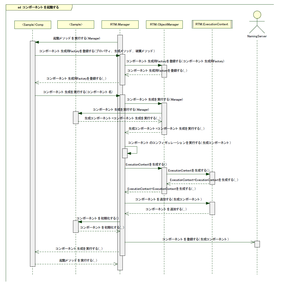
Here is the behavior when RT-Components for C++ start. This is basically same as the behavior when RT-Components for Java start, however separation of main body of RT-Components for to XXXImpl classes change receivers of message which are sent when components are created and when components are initialized, to XXX classes.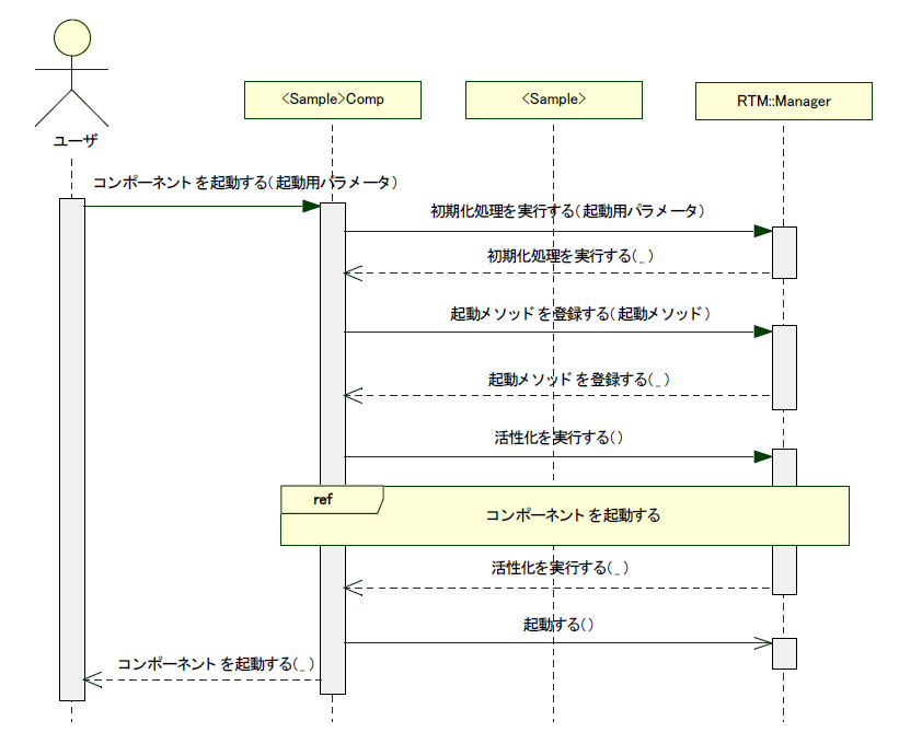
Relationship between IDL data types and Java language data types
Table 3-4 shows the relationship between CORBA IDL data types and Java language data types.
| CORBA IDL | Java language |
| short | short |
| long | int |
| float | float |
| double | double |
| long long | long |
| long double | double |
| char | char |
| wchar | char |
| octet | byte |
| unsigned short | short |
| unsigned long | int |
| unsigned long long | long |
| boolean | boolean |
| string | String |
| wstring | String |
| any | org.omg.CORBA.Any |
| void | void |
Others
Tips
Configuration to Start up Eclipse automatically
- On Windows
- 1. Select a ".project" file from the directory of Eclipse project, and right-click to select [Properties]from the shown context menu.
Note: you can select any Eclipse project.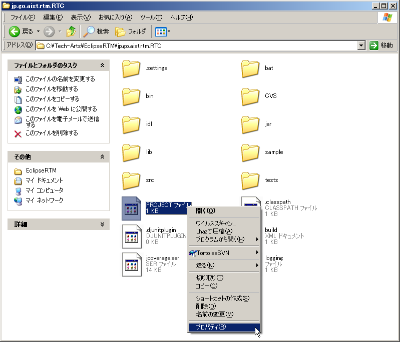 Fig.3-22 Selecting a ".project" file
- 1. Select a ".project" file from the directory of Eclipse project, and right-click to select [Properties]from the shown context menu.
- 2. Click [Change] button which is in the right of "Program" line center at "General" tab in the displayed "Properties" dialog.
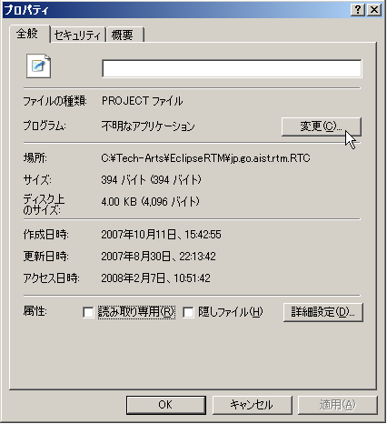 Fig.3-23 Changing an association with an application
- 3. Click [Browse] button lower in "Open With" dialog.
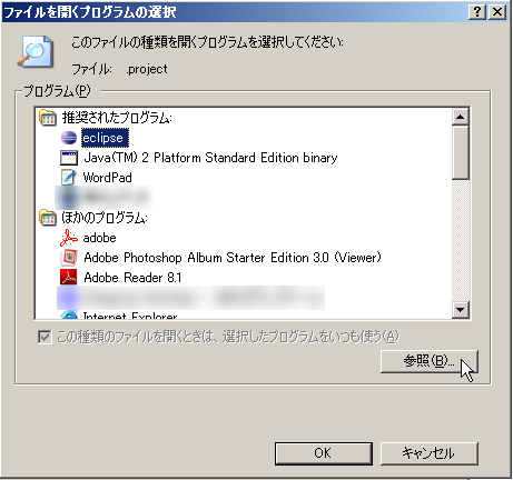 Fig.3-24 Selecting Eclipse
- 4. A dialog to select a file is shown, Go to the directory in which Eclipse you want to start up automatically existes, and select "Eclipse.exe".
- 5. Press [OK] to close "Open With" dialog and "Properties" dialog.
::Once you set up as above, you can double-click a ".project" file to run the version of Eclipse you specified automatically.
|
::Note You must notice that the version you specified is always started up, even if several versions of Eclipse are installed.
|- Note When the project you clicked is not included in the workspace set up for the starting Eclipse, the project does not appear in Package Explorer of the Eclipse. In this case, you need to import the target project to the workspace, or switch to another workspace.
--On Linux
You can specify a workspace with a data option when you start up Eclipse.> eclipse ?data /home/devel/OpenRTM/workspace
- Please specify the workspace which contains the target project.
Acknowledgments
OpenRTM-aist Java was developed using the following libraries. We would like to extend out thanks to anyone who was involved in the designing and developing of these projects.
Apache Commons CLI 1.1
This product includes software developed by The Apache Software Foundation (http://www.apache.org/ ).
Development of RT Component(OpenCV Components for RTCB-RC1)
はじめに
ここでは、OpenCV ライブラリを VC9 にて RTコンポーネント化する手順を紹介します。
OpenCVとは
OpenCVとはインテルが開発・公開しているオープンソースのコンピュータービジョン向けライブラリです。
Wikipediaより抜粋。
作成する RTコンポーネント
- Flip コンポーネント: OpenCV ライブラリのうち、cvFlip() 関数を用いて画像の反転を行う RTコンポーネント。
- ObjectTracking コンポーネント: OpenCV ライブラリを使用し、マウスで選択した対象物を追跡するコンポーネント。 追跡中の画像表示、追跡画像を OutPort から出力、追跡対象の移動量を OutPort から出力などの機能を持つ。
OpenCV ライブリの RTコンポーネント化 (Flipコンポーネント)
ここでは、OpenCV ライブラリのうち、画像の反転を行う cvFlip() を VC9 にて RTコンポーネント化します。
以下は、作業の流れです。
- cvFlip 関数について
- コンポーネントの概要
- 動作環境・開発環境
- Flip コンポーネントの雛型の生成
- アクティビティ処理の実装
- コンポーネントの動作確認
cvFlip 関数について
cvFlip 関数は、2次元配列を垂直、水平、または両軸で反転します。
void cvFlip(IplImage* src, IplImage* dst=NULL, int flip_mode=0); #define cvMirror cvFlip src 入力配列 dst 出力配列。もし dst=NULL であれば、src が上書きされます。 flip_mode 配列の反転方法の指定内容: flip_mode = 0: X軸周りでの反転(上下反転) flip_mode > 0: Y軸周りでの反転(左右反転) flip_mode < 0: 両軸周りでの反転(上下左右反転)
コンポーネントの概要
InPort からの入力画像を反転し OutPort から出力するコンポーネント。
反転の対象軸は、RTCのコンフィギュレーション機能を使用して flip_mode という名前のパラメーターで指定します。
flip_mode は、反転したい方向に応じて下記のように指定してください。
- 上下反転したい場合、0
- 左右反転したい場合、1
- 上下左右反転したい場合、-1
作成する RTC の仕様は以下のとおりです。
- InPort
- キャプチャされた画像データ (TimedOctetSeq)
- OutPort
- 反転した画像データ (TimedOctetSeq)
- Configuration
- 反転方法の指定 (int)
※ TimedOctetSeq型は、OpenRTM-aist の BasicDataType.idl にて下記のように定義されているデータ型です。
※ octet型とは、CORBA IDL の基本型で、転送時にいかなるデータ変換も施されないことが保証されている8ビット値です。
struct Time
{
unsigned long sec; // sec
unsigned long nsec; // nano sec
};
struct TimedOctetSeq
{
Time tm;
sequence<octet> data;
};
図1は、それぞれのflip_mode での画像処理のイメージ図です。

動作環境・開発環境
- OS: Windows XP SP2
- コンパイラ: Visual C++ 2008 Express Edition 日本語版
- omniORB: version 4.1.2
- OpenCV: version 1.0
- OpenRTM-aist: version 1.0.0-RC1
- RTSystemEditor 1.0
- RTCBuilder 1.0
Flip コンポーネントの雛型の生成
Flip コンポーネントの雛型の生成は、RTCBuilder を用いて行います。
RTCBuilder の起動
新規ワークスペースを指定して Eclipse を起動すると、以下の「ようこそ」画面が表示されます。 この 「ようこそ」画面の左上の「X」をクリックすると以下の画面が表示されます。

右上の [Open Perspective] ボタンをクリックし、プルダウンの「Other…」を選択します。

「RTC Builder」を選択し、[OK] ボタンをクリックします。

RTCBuilder が起動します。

RTCBuilder 用プロジェクトの作成
まず最初に、RT コンポーネントを作成するための Eclipse プロジェクトを作成します。 画面上部のメニューから[ファイル] > [新規] > [プロジェクト] を選択します。

表示された「新規プロジェクト」画面において、[その他] > [RTC ビルダ] を選択し、[次へ] をクリックします。

「プロジェクト名」欄に作成するプロジェクト名を入力して [完了] をクリックします。
指定した名称のプロジェクトが生成され、パッケージエクスプローラー内に追加されます。

生成したプロジェクト内には、デフォルト値が設定された RTC プロファイル XML(RTC.xml) が自動的に生成されます。
データポートで使用するデータタイプ定義ファイルの在り処の設定
データポートやサービスポートで使用するデータ型が定義された IDL ファイルが置いてある場所を予め設定しておく必要があります。
※ ここでの設定内容は、ワークスペースを変更しない限り有効ですので、プロジェクト毎に設定する必要はありません。
下記の手順にて、データ型が定義されている IDL ファイルの在り処を設定して下さい。
1. メニューバーの [ウィンドウ] > [設定] をクリックし、設定ダイアログを表示させます。
2. [RtcBuilder] > [Data Type] をクリックし、図12の Data Type 入力画面を出します。
3. Data Type入力画面の [Add] ボタンをクリックし、"IDL File Directories"を入力します。
OpenRTM-aist で定義されているデータ型の IDL ファイルはデフォルトでは下記にインストールされます。
C:\Program Files\OpenRTM-aist\1.0\rtm\idl
4. [OK] ボタンをクリックし、設定を終了します。

RTC プロファイルエディタの起動
RTC プロファイルエディタを開くには、ツールバーの [Open New RtcBuilder Editor] ボタンをクリックするか、メニューの [ファイル] > [Open New Builder Editor] を選択します。


コンポーネントのプロファイル情報入力とコードの生成
1. 「基本」タブを選択し、基本情報を入力します。
-Module name: Flip
- Module description: Flip image component
- Module version: 1.0.0
- Module vender: AIST
- Module category: Category
- Component type: STATIC
- Component's activity type: PERIODIC
- Component kind: DataFlowComponent
- Number of maximum instance: 1
- Execution type: PeriodicExecutionContext
- Execution Rate: 1.0
-Output Project: Flip

2. 「アクティビティ」タブを選択し、使用するアクションコールバックを指定します。
Flipコンポーネントでは、onActivated()、onDeactivated()、onExecute() コールバックを使用しますので、 図14のようにon_activated、on_deactivated、on_executeの3つにチェックを入れます。

3. 「データポート」タブを選択し、データポートの情報を入力します。
- InPort Profile:
- Port Name: original_image
- Data Type: TimedOctetSeq
- Var Name: image_orig
- Disp. Position: left
- OutPort Profile:
- Port Name: fliped_image
- Data Type: TimedOctetSeq
- Var Name: image_flip
- Disp. Position: right

4. 「コンフィギュレーション」タブを選択し、Configuration の変数を入力します。
- flip_mode
- Name: flip_mode
- TYpe: int
- Default Value: 1
- 変数名: flip_mode
- image_height
- Name: image_height
- TYpe: int
- Default Value: 240
- 変数名: img_height
- image_width
- Name: image_width
- TYpe: int
- Default Value: 320
- 変数名: img_width

5. 「言語・環境」タブを選択し、プログラミング言語を選択します。
今回は、C++(言語) を選択します。

6. 「基本」タブにある [コード生成] ボタンをクリックし、コンポーネントの雛型を生成します。

※ 生成されるコード群は、Eclipse 起動時に指定したワークスペースフォルダーの中に生成されます。現在のワークスペースは、[ファイル] > [ワークスペースの切り替え] で確認することができます。
アクティビティ処理の実装
Flip コンポーネントでは、InPort から受け取った画像を画像保存用バッファに保存し、その保存した画像を OpenCV の cvFlip() 関数にて変換します。その後、変換された画像を OutPort から送信します。
onActivated()、onExecute()、onDeactivated()での処理内容を図19に示します。

onExecute() での処理を図20に示します。

OpenCV 用ユーザープロパティシートのコピー
プロパティシートとは、コンパイルに必要な種々のオプション(インクルードパス、ライブラリロードバス、ライブラリ)やマクロを記述した VC の設定ファイルの一種です。 RTCBuilder や rtc-template で生成した VC 用のプロジェクトでは、VC のプロパティシートを使用して各種オプションを与えています。また、ユーザーがオプションを追加できるように、ユーザー定義のプロパティシートもインクルードするようになっています。- rtm_config.vsprop:OpenRTM に関する情報を含むプロパティシート。インストールされている OpenRTM-aist に依存するファイルであるため、copyprops.bat を使用して OpenRTM のシステムディレクトリーからカレントのプロジェクトへコピーします。
- user_config.vsprops:ユーザー定義のプロパティシート。デフォルトでは空っぽです。使い方は、ソースコード:OpenRTM-aist/win32/OpenRTM-aist/example/USBCamera の中に入っている user_config.vsprops (OpenCV 用の設定)を参考にしてください。
以下の内容を user_config.vsprops というファイル名で保存し、Flip フォルダーにコピーしてください。
もしくは、下記より vsprops ファイルをダウンロードし、Flip フォルダーに保存してください。
※ 既にFlipフォルダーには user_config.vsprops ファイルが存在しておりますが、上書きして構いません。
<?xml version="1.0" encoding="shift_jis"?>
<VisualStudioPropertySheet
ProjectType="Visual C++"
Version="8.00"
Name="OpenCV"
>
<Tool
Name="VCCLCompilerTool"
AdditionalIncludeDirectories="$(cv_includes)"
/>
<Tool
Name="VCLinkerTool"
AdditionalLibraryDirectories="$(cv_libdir)"
/>
<UserMacro
Name="user_lib"
Value="$(cv_lib)"
/>
<UserMacro
Name="user_libd"
Value="$(cv_libd)"
/>
<UserMacro
Name="cv_root"
Value="C:\Program Files\OpenCV"
/>
<UserMacro
Name="cv_includes"
Value=""$(cv_root)\cv\include";"$(cv_root)\cvaux\include";"$(cv_root)\cxcore\include";"$(cv_root)\otherlibs\highgui";"$(cv_root)\otherlibs\cvcam\include""
/>
<UserMacro
Name="cv_libdir"
Value=""$(cv_root)\lib""
/>
<UserMacro
Name="cv_bin"
Value="$(cv_root)\bin"
/>
<UserMacro
Name="cv_lib"
Value="cv.lib cvcam.lib highgui.lib cxcore.lib"
/>
<UserMacro
Name="cv_libd"
Value="cv.lib cvcam.lib highgui.lib cxcore.lib"
/>
</VisualStudioPropertySheet>copyprops.bat の実行
copyprops.bat というファイルを実行することで、rtm_config.vsprops というファイルがコピーされます。
rtm_config.vsprops ファイルは、RTコンポーネントを VC++ でビルドするために必要なインクルードパスやリンクするライブラリ等が記述されたファイルです。
ヘッダファイルの編集
- OpenCV のライブラリを使用するため、OpenCV のインクルードファイルをインクルードします。
//OpenCV 用インクルードファイルのインクルード #include<cv.h> #include<cxcore.h> #include<highgui.h>
- この cvFlip コンポーネントでは、画像領域の確保、Flip 処理、確保した画像領域の解放のそれぞれの処理を行います。これらの処理は、それぞれ onActivated()、onDeactivated()、onExecute() のコールバック関数で呼ぶことにしますので、これら3つの関数のコメントアウトを解除します。
/***
*
* The activated action (Active state entry action)
* former rtc_active_entry()
*
* @param ec_id target ExecutionContext Id
*
* @return RTC::ReturnCode_t
*
*
*/
virtual RTC::ReturnCode_t onActivated(RTC::UniqueId ec_id);
/***
*
* The deactivated action (Active state exit action)
* former rtc_active_exit()
*
* @param ec_id target ExecutionContext Id
*
* @return RTC::ReturnCode_t
*
*
*/
virtual RTC::ReturnCode_t onDeactivated(RTC::UniqueId ec_id);
/***
*
* The execution action that is invoked periodically
* former rtc_active_do()
*
* @param ec_id target ExecutionContext Id
*
* @return RTC::ReturnCode_t
*
*
*/
virtual RTC::ReturnCode_t onExecute(RTC::UniqueId ec_id);- 反転した画像の保存用にメンバー変数を追加します。
IplImage* m_image_buff; IplImage* m_flip_image_buff;
ソースファイルの編集
下記のように、onActivated()、onDeactivated()、onExecute()を実装します。
RTC::ReturnCode_t Flip::onActivated(RTC::UniqueId ec_id)
{
// イメージ用メモリーの確保
m_image_buff = cvCreateImage(cvSize(m_img_width, m_img_height), IPL_DEPTH_8U, 3);
m_flip_image_buff = cvCreateImage(cvSize(m_img_width, m_img_height), IPL_DEPTH_8U, 3);
return RTC::RTC_OK;
}
RTC::ReturnCode_t Flip::onDeactivated(RTC::UniqueId ec_id)
{
// イメージ用メモリーの解放
cvReleaseImage(&m_image_buff);
cvReleaseImage(&m_flip_image_buff);
return RTC::RTC_OK;
}
RTC::ReturnCode_t Flip::onExecute(RTC::UniqueId ec_id)
{
// 新しいデータのチェック
if (m_image_origIn.isNew()) {
// InPortデータの読み込み
m_image_origIn.read();
// InPortの画像データをIplImageのimageDataにコピー
memcpy(m_image_buff->imageData,(void *)&(m_image_orig.data[0]),m_image_orig.data.length());
// InPortからの画像データを反転する。 m_flip_mode 0: X軸周り, 1: Y軸周り, -1: 両方の軸周り
cvFlip(m_image_buff, m_flip_image_buff, m_flip_mode);
// 画像データのサイズ取得
int len = m_flip_image_buff->nChannels * m_flip_image_buff->width * m_flip_image_buff->height;
m_image_flip.data.length(len);
// 反転した画像データを OutPort にコピー
memcpy((void *)&(m_image_flip.data[0]),m_flip_image_buff->imageData,len);
// 反転した画像データを OutPort から出力する。
m_image_flipOut.write();
}
return RTC::RTC_OK;
}ビルドの実行
図21のようにし、コンポーネントのビルドを行います。

Flip コンポーネントの動作確認
ここでは、OpenRTM-aist のサンプルコンポーネントに含まれている USBCameraAqcuireComp コンポーネントと、USBCameraMonitorCom コンポーネント、それと、Flip コンポーネントを接続し動作確認を行います。
NameService の起動
omniORB のネームサービスを起動します。
[スタート] > [すべてのプログラム] > [OpenRTM-aist] > [C++] > [examples] をクリックし、[Start Naming Service] をクリックしてください。
rtc.conf の作成
RTコンポーネントでは、ネームサーバーのアドレスやネームサーバーへの登録フォーマットなどの情報を rtc.conf というファイルで指定する必要があります。
下記の内容を rtc.conf というファイル名で保存し、Flip\FlipComp\Debug (もしくは、Release) フォルダーに置いてください。
 corba.nameservers: localhost
 naming.formats: %n.rtc
Flip コンポーネントの起動
Flip コンポーネントを起動します。
先程 rtc.conf ファイルを置いたフォルダーにある、FlipComp.exe ファイルを実行してください。
USBCameraAqcuire、USBCameraMonitor コンポーネントの起動
USB カメラのキャプチャ画像を OutPort から出力する USBCameraAqcuireComp コンポーネントと、InPort で受け取った画像を画面に表示する USBCameraMonitorCOmp コンポーネントを起動します。
これら2つのコンポーネントは、下記の手順にて起動できます。
[スタート] > [すべてのプログラム] > [OpenRTM-aist] > [C++] > [examples] をクリックし、「USBCameraAqcuireComp」と「USBCameraMonitorCOmp」をそれぞれクリックして実行します。
コンポーネントの接続
図22のように、RTSystemEditor にて USBCameraAqcuireComp,Flip、USBCameraMonitorComp コンポーネントを接続します。

Flip コンポーネントのコンフィギュレーションの変更
図23のようにコンフィギュレーションビューにてコンフィギュレーションを変更することができます。
ELECOM製 の UCAM-DLM 130HWH (白いUSBカメラ) を使用の場合は、image_height と image_width パラメーターを下記のように変更してください。
image_height : 480 image_width : 640
また、ELECOM製 の UCAM-DLM 130HWH (白いUSBカメラ) を使用の場合は、USBCameraMonitor の image_height,image_width パラメーターも 上記のように変更する必要があります。

コンポーネントの Activate
RTSystemEditor の上部にあります「ALL」というアイコンをクリックし、全てのコンポーネントをアクティベートします。
正常にアクティベートされた場合、図24のように黄緑色でコンポーネントが表示されます。

動作確認
Flip コンポーネントのコンフィギュレーションパラメーター「flip_mode」を「0」や「-1」などに変更し、画像の反転が行われるかを確認してください。
Flip コンポーネントのソースファイル
// -*- C++ -*-
/*!
* @file Flip.cpp
* @brief Flip image component
* @date $Date$
*
* $Id$
*/
#include "Flip.h"
// Module specification
static const char* flip_spec[] =
{
"implementation_id", "Flip",
"type_name", "Flip",
"description", "Flip image component",
"version", "1.0.0",
"vendor", "AIST",
"category", "Category",
"activity_type", "PERIODIC",
"kind", "DataFlowComponent",
"max_instance", "1",
"language", "C++",
"lang_type", "compile",
"exec_cxt.periodic.rate", "1.0",
// Configuration variables
"conf.default.flip_mode", "1",
"conf.default.image_height", "240",
"conf.default.image_width", "320",
""
};
/*!
* @brief constructor
* @param manager Maneger Object
*/
Flip::Flip(RTC::Manager* manager)
: RTC::DataFlowComponentBase(manager),
m_image_origIn("original_image", m_image_orig),
m_image_flipOut("fliped_image", m_image_flip),
dummy(0),
m_image_buff(0),
m_flip_image_buff(0)
{
// Registration: InPort/OutPort/Service
// Set InPort buffers
registerInPort("original_image", m_image_origIn);
// Set OutPort buffer
registerOutPort("fliped_image", m_image_flipOut);
}
/*!
* @brief destructor
*/
Flip::~Flip()
{
}
RTC::ReturnCode_t Flip::onInitialize()
{
// Bind variables and configuration variable
bindParameter("flip_mode", m_flip_mode, "1");
bindParameter("image_height", m_img_height, "240");
bindParameter("image_width", m_img_width, "320");
return RTC::RTC_OK;
}
RTC::ReturnCode_t Flip::onActivated(RTC::UniqueId ec_id)
{
// イメージ用メモリーの確保
m_image_buff = cvCreateImage(cvSize(m_img_width, m_img_height), IPL_DEPTH_8U, 3);
m_flip_image_buff = cvCreateImage(cvSize(m_img_width, m_img_height), IPL_DEPTH_8U, 3);
return RTC::RTC_OK;
}
RTC::ReturnCode_t Flip::onDeactivated(RTC::UniqueId ec_id)
{
// イメージ用メモリーの解放
cvReleaseImage(&m_image_buff);
cvReleaseImage(&m_flip_image_buff);
return RTC::RTC_OK;
}
RTC::ReturnCode_t Flip::onExecute(RTC::UniqueId ec_id)
{
// 新しいデータのチェック
if (m_image_origIn.isNew()) {
// InPort データの読み込み
m_image_origIn.read();
// InPortの 画像データを IplImage の imageData にコピー
memcpy(m_image_buff->imageData,(void *)&(m_image_orig.data[0]),m_image_orig.data.length());
// InPortからの画像データを反転する。 m_flip_mode 0: X軸周り, 1: Y軸周り, -1: 両方の軸周り
cvFlip(m_image_buff, m_flip_image_buff, m_flip_mode);
// 画像データのサイズ取得
int len = m_flip_image_buff->nChannels * m_flip_image_buff->width * m_flip_image_buff->height;
m_image_flip.data.length(len);
// 反転した画像データを OutPort にコピー
memcpy((void *)&(m_image_flip.data[0]),m_flip_image_buff->imageData,len);
// 反転した画像データを OutPort から出力する。
m_image_flipOut.write();
}
return RTC::RTC_OK;
}
extern "C"
{
void FlipInit(RTC::Manager* manager)
{
RTC::Properties profile(flip_spec);
manager->registerFactory(profile,
RTC::Create<Flip>,
RTC::Delete<Flip>);
}
};Flip コンポーネントのヘッダファイル
// -*- C++ -*-
/*!
* @file Flip.h
* @brief Flip image component
* @date $Date$
*
* $Id$
*/
#ifndef FLIP_H
#define FLIP_H
#include <rtm/Manager.h>
#include <rtm/DataFlowComponentBase.h>
#include <rtm/CorbaPort.h>
#include <rtm/DataInPort.h>
#include <rtm/DataOutPort.h>
#include <rtm/idl/BasicDataTypeSkel.h>
// (1) OpenCV 用インクルードファイルのインクルード
#include<cv.h>
#include<cxcore.h>
#include<highgui.h>
using namespace RTC;
/*!
* @class Flip
* @brief Flip image component
*
*/
class Flip
: public RTC::DataFlowComponentBase
{
public:
/*!
* @brief constructor
* @param manager Maneger Object
*/
Flip(RTC::Manager* manager);
/*!
* @brief destructor
*/
~Flip();
/*!
*
* The initialize action (on CREATED->ALIVE transition)
* formaer rtc_init_entry()
*
* @return RTC::ReturnCode_t
*
*
*/
virtual RTC::ReturnCode_t onInitialize();
   /***
    *
    * The activated action (Active state entry action)
    * former rtc_active_entry()
    *
    * @param ec_id target ExecutionContext Id
    *
    * @return RTC::ReturnCode_t
    *
    *
    */
   virtual RTC::ReturnCode_t onActivated(RTC::UniqueId ec_id);

   /***
    *
    * The deactivated action (Active state exit action)
    * former rtc_active_exit()
    *
    * @param ec_id target ExecutionContext Id
    *
    * @return RTC::ReturnCode_t
    *
    *
    */
   virtual RTC::ReturnCode_t onDeactivated(RTC::UniqueId ec_id);

   /***
    *
    * The execution action that is invoked periodically
    * former rtc_active_do()
    *
    * @param ec_id target ExecutionContext Id
    *
    * @return RTC::ReturnCode_t
    *
    *
    */
   virtual RTC::ReturnCode_t onExecute(RTC::UniqueId ec_id);
protected:
// Configuration variable declaration
/*!
* flip_mode = 0: flipping around x-axis
* flip_mode > 1: flipping around y-axis
* flip_mode < 0: flipping around both axises
* - Name: flip_mode flip_mode
* - DefaultValue: 1
*/
int m_flip_mode;
/*!
*
* - Name: m_img_height
* - DefaultValue: 240
* - 画像の高さ
*/
int m_img_height;
/*!
*
* - Name: m_img_width
* - DefaultValue: 320
* - 画像の幅
*/
int m_img_width;
// DataInPort declaration
TimedOctetSeq m_image_orig;
InPort<TimedOctetSeq> m_image_origIn;
// DataOutPort declaration
TimedOctetSeq m_image_flip;
OutPort<TimedOctetSeq> m_image_flipOut;
private:
int dummy;
   IplImage* m_image_buff;
   IplImage* m_flip_image_buff;
};
extern "C"
{
void FlipInit(RTC::Manager* manager);
};
#endif // FLIP_HFlip コンポーネントのビルド済みパッケージ
ビルド済みパッケージを下記からダウンロードできます。
拡張子を"zip_"としてますので、"zip"にリネームしてから解凍して下さい。
おまけ(物体追跡コンポーネント)
OpenCVのライブラリを用いて、物体追跡を行うコンポーネントです。
コンポーネントの概要
InPort からの画像データを表示し、マウスで選択されたオブジェクトを追跡するコンポーネント。
OutPort からは、物体追跡画像と、マウスで選択した位置からの移動量を出力する。
画像のサイズと、明度、彩度はコンフィグレーションにて変更可能。
作成する RTC の仕様は以下のとおりです。
- InPort
- キャプチャされた画像データ (TimedOctetSeq)
- OutPort
- 物体追跡画像データ (TimedOctetSeq)
- OutPort
- マウスで選択したオブジェクトの中心位置の移動量 (TimedFloatSeq)
- Configuration
- 明度の最大値(int) default: 256
- 明度の最小値(int) default: 10
- 彩度の最小値(int) default: 30
- 画像の高さ(int) default: 240
- 画像の幅(int) default: 320
RTCBuilder でのプロファイル情報入力内容
基本情報
- Module name: ObjectTracking
- Module description: Object tracking component
- OutputProject: ObjectTracking
データポート
- InPort Profile:
- Port Name: in_image
- Data Type: TimedOctetSeq
- Var Name: in_image
- Disp. Position: left
- OutPort Profile:
- Port Name: tracing_image
- Data Type: TimedOctetSeq
- Var Name: tracking_image
- Disp. Position: right
- OutPort Profile:
- Port Name: displacement
- Data Type: TimedFloatSeq
- Var Name: displacement
- Disp. Position: right
コンフィギュレーションパラメーター
- brightness_max
- Name: brightness_max
- TYpe: int
- Default Value: 256
- 変数名: b_max
- brightness_min
- Name: brightness_min
- TYpe: int
- Default Value: 10
- 変数名: b_min
- saturation_min
- Name: saturation_min
- TYpe: int
- Default Value: 30
- 変数名: s_min
- image_height
- Name: image_height
- TYpe: int
- Default Value: 240
- 変数名: img_height
- image_width
- Name: image_width
- TYpe: int
- Default Value: 320
- 変数名: img_width
ObjectTracking コンポーネントのソースファイル
// -*- C++ -*-
/*!
* @file ObjectTracking.cpp
* @brief Object tracking component
* @date $Date$
*
* $Id$
*/
#include "ObjectTracking.h"
#define HIST_RANGE_MAX 180.0
#define HIST_RANGE_MIN 0.0
// 入力画像用 IplImage
IplImage* g_image;
// CamShift トラッキング用変数
CvPoint g_origin;
CvRect g_selection; //
// 初期追跡領域の設定判別フラグ値 (0: 設定なし, 1: 設定あり)
int g_select_object;
// トラッキングの開始/停止用フラグ値 (0: 停止, -1: 開始, 1: トラッキング中)
int g_track_object;
// オブジェクト選択判定用フラグ(0: 1以外 1: 選択された直後)
int g_selected_flag;
// 選択された範囲の中心座標
float g_selected_x;
float g_selected_y;
// Module specification
static const char* objecttracking_spec[] =
{
"implementation_id", "ObjectTracking",
"type_name", "ObjectTracking",
"description", "Object tracking component",
"version", "1.0.0",
"vendor", "AIST",
"category", "Category",
"activity_type", "PERIODIC",
"kind", "DataFlowComponent",
"max_instance", "1",
"language", "C++",
"lang_type", "compile",
"exec_cxt.periodic.rate", "1.0",
// Configuration variables
"conf.default.brightness_max", "256",
"conf.default.brightness_min", "10",
"conf.default.saturation_min", "30",
"conf.default.image_height", "240",
"conf.default.image_width", "320",
""
};
/*!
* @brief constructor
* @param manager Maneger Object
*/
ObjectTracking::ObjectTracking(RTC::Manager* manager)
: RTC::DataFlowComponentBase(manager),
m_in_imageIn("in_image", m_in_image),
m_tracking_imageOut("tracing_image", m_tracking_image),
m_displacementOut("displacement", m_displacement),
dummy(0),
m_hsv(0), m_hue(0), m_mask(0), m_backproject(0),
m_hist(0), m_backproject_mode(0),m_hdims(16),
m_init_flag(0)
{
// Registration: InPort/OutPort/Service
// Set InPort buffers
registerInPort("in_image", m_in_imageIn);
// Set OutPort buffer
registerOutPort("tracing_image", m_tracking_imageOut);
registerOutPort("displacement", m_displacementOut);
m_hranges_arr[0] = HIST_RANGE_MIN;
m_hranges_arr[1] = HIST_RANGE_MAX;
m_hranges = m_hranges_arr;
}
/*!
* @brief destructor
*/
ObjectTracking::~ObjectTracking()
{
}
RTC::ReturnCode_t ObjectTracking::onInitialize()
{
// Bind variables and configuration variable
bindParameter("brightness_max", m_b_max, "256");
bindParameter("brightness_min", m_b_min, "10");
bindParameter("saturation_min", m_s_min, "30");
bindParameter("image_height", m_img_height, "240");
bindParameter("image_width", m_img_width, "320");
m_displacement.data.length(2);
return RTC::RTC_OK;
}
RTC::ReturnCode_t ObjectTracking::onActivated(RTC::UniqueId ec_id)
{
m_init_flag = 0;
// ウインドウを生成する
cvNamedWindow( "ObjectTracking", 1 );
// マウス操作時のコールバック処理の登録
cvSetMouseCallback( "ObjectTracking", on_mouse, 0 );
g_selected_flag = 0;
g_selected_x = 0.0;;
g_selected_y = 0.0;;
return RTC::RTC_OK;
}
RTC::ReturnCode_t ObjectTracking::onDeactivated(RTC::UniqueId ec_id)
{
if (m_init_flag) {
// メモリーを解放する
cvReleaseImage(&g_image);
cvReleaseImage(&m_hsv);
cvReleaseImage(&m_hue);
cvReleaseImage(&m_mask);
cvReleaseImage(&m_backproject);
}
// ウインドウを破棄する
cvDestroyWindow("ObjectTracking");
m_init_flag = 0;
return RTC::RTC_OK;
}
RTC::ReturnCode_t ObjectTracking::onExecute(RTC::UniqueId ec_id)
{
if (m_in_imageIn.isNew()) {
m_in_imageIn.read();
if(!m_init_flag) allocateBuffers();
memcpy(g_image->imageData,(void *)&(m_in_image.data[0]),m_in_image.data.length());
cvShowImage("ObjectTracking", g_image);
// キャプチャされた画像を HSV 表色系に変換して hsv に格納
cvCvtColor( g_image, m_hsv, CV_BGR2HSV );
// g_track_objectフラグが0以下なら、以下の処理を行う
if( g_track_object )
{
cvInRangeS( m_hsv, cvScalar(HIST_RANGE_MIN,m_s_min,MIN(m_b_min,m_b_max),0),
cvScalar(HIST_RANGE_MAX,256,MAX(m_b_min,m_b_max),0), m_mask );
cvSplit( m_hsv, m_hue, 0, 0, 0 );
if( g_track_object < 0 ) calcHistogram();
// バックプロジェクションを計算する
cvCalcBackProject( &m_hue, m_backproject, m_hist );
// backProjectionのうち、マスクが1であるとされた部分のみ残す
cvAnd( m_backproject, m_mask, m_backproject, 0 );
// CamShift法による領域追跡を実行する
cvCamShift( m_backproject, m_track_window,
cvTermCriteria( CV_TERMCRIT_EPS | CV_TERMCRIT_ITER, 10, 1 ),
&m_track_comp, &m_track_box );
m_track_window = m_track_comp.rect;
if( m_backproject_mode )
cvCvtColor( m_backproject, g_image, CV_GRAY2BGR );
if( g_image->origin )
m_track_box.angle = -m_track_box.angle;
cvEllipseBox( g_image, m_track_box, CV_RGB(255,0,0), 3, CV_AA, 0 );
// マウスで選択された領域の中心座標を保存
if (g_selected_flag) {
g_selected_x = m_track_box.center.x;
g_selected_y = m_track_box.center.y;
g_selected_flag = 0;
}
// マウスで選択された位置からの移動量をOutPortから出力
m_displacement.data[0] = m_track_box.center.x - g_selected_x;
m_displacement.data[1] = -(m_track_box.center.y - g_selected_y);
m_displacementOut.write();
}
// マウスで選択中の初期追跡領域の色を反転させる
if( g_select_object && g_selection.width > 0 && g_selection.height > 0 )
{
cvSetImageROI( g_image, g_selection );
cvXorS( g_image, cvScalarAll(255), g_image, 0 );
cvResetImageROI( g_image );
}
// 画像を表示する
cvShowImage( "ObjectTracking", g_image );
// 画像をOutPortから出力する
int len = g_image->nChannels * g_image->width * g_image->height;
m_tracking_image.data.length(len);
memcpy((void *)&(m_tracking_image.data[0]),g_image->imageData,len);
m_tracking_imageOut.write();
// キー入力を待ち、押されたキーによって処理を分岐させる
int c = cvWaitKey(10);
// while無限ループから脱出(プログラムを終了)
if( (char) c == 27 ) {
this->exit();
}
}
return RTC::RTC_OK;
}
/*!
* 全てのイメージ用メモリーの確保
*/
void ObjectTracking::allocateBuffers() {
g_image = cvCreateImage( cvSize(m_img_width,m_img_height),8, 3 );
m_hsv = cvCreateImage( cvSize(m_img_width,m_img_height),8, 3 );
m_hue = cvCreateImage( cvSize(m_img_width,m_img_height),8, 1 );
m_mask = cvCreateImage( cvSize(m_img_width,m_img_height),8, 1 );
m_backproject = cvCreateImage( cvSize(m_img_width,m_img_height),8, 1 );
m_hist = cvCreateHist( 1, &m_hdims, CV_HIST_ARRAY, &m_hranges, 1 );
m_init_flag = 1;
}
/*!
* ヒストグラムの計算
*/
void ObjectTracking::calcHistogram() {
float max_val = 0.f;
cvSetImageROI( m_hue, g_selection );
cvSetImageROI( m_mask, g_selection );
// ヒストグラムを計算し、最大値を求める
cvCalcHist( &m_hue, m_hist, 0, m_mask );
cvGetMinMaxHistValue( m_hist, 0, &max_val, 0, 0 );
// ヒストグラムの縦軸(頻度)を0-255のダイナミックレンジに正規化
cvConvertScale( m_hist->bins, m_hist->bins, max_val ? 255. / max_val : 0., 0 );
// hue,mask画像に設定された ROI をリセット
cvResetImageROI( m_hue );
cvResetImageROI( m_mask );
m_track_window = g_selection;
// track_object をトラッキング中にする
g_track_object = 1;
}
extern "C"
{
void ObjectTrackingInit(RTC::Manager* manager)
{
RTC::Properties profile(objecttracking_spec);
manager->registerFactory(profile,
RTC::Create<ObjectTracking>,
RTC::Delete<ObjectTracking>);
}
//
// マウスドラッグによって初期追跡領域を指定する
//
// 引数:
// event : マウス左ボタンの状態
// x : マウスが現在ポイントしているx座標
// y : マウスが現在ポイントしているy座標
// flags : 本プログラムでは未使用
// param : 本プログラムでは未使用
//
void on_mouse( int event, int x, int y, int flags, void* param )
{
// 画像が取得されていなければ、処理を行わない
if( !g_image )
return;
// 原点の位置に応じてyの値を反転(画像の反転ではない)
if( g_image->origin )
y = g_image->height - y;
// マウスの左ボタンが押されていれば以下の処理を行う
if( g_select_object )
{
g_selection.x = MIN(x,g_origin.x);
g_selection.y = MIN(y,g_origin.y);
g_selection.width = g_selection.x + CV_IABS(x - g_origin.x);
g_selection.height = g_selection.y + CV_IABS(y - g_origin.y);
g_selection.x = MAX( g_selection.x, 0 );
g_selection.y = MAX( g_selection.y, 0 );
g_selection.width = MIN( g_selection.width, g_image->width );
g_selection.height = MIN( g_selection.height, g_image->height );
g_selection.width -= g_selection.x;
g_selection.height -= g_selection.y;
}
// マウスの左ボタンの状態によって処理を分岐
switch( event )
{
case CV_EVENT_LBUTTONDOWN:
// マウスの左ボタンが押されたのであれば、
// 原点および選択された領域を設定
g_origin = cvPoint(x,y);
g_selection = cvRect(x,y,0,0);
g_select_object = 1;
break;
case CV_EVENT_LBUTTONUP:
// マウスの左ボタンが離されたとき、width と height がどちらも正であれば、
// g_track_objectフラグを開始フラグにする
g_select_object = 0;
if( g_selection.width > 0 && g_selection.height > 0 ) {
g_track_object = -1;
g_selected_flag = 1;
}
break;
}
}
};ObjectTracking コンポーネントのヘッダファイル
// -*- C++ -*-
/*!
* @file ObjectTracking.h
* @brief Object tracking component
* @date $Date$
*
* $Id$
*/
#ifndef OBJECTTRACKING_H
#define OBJECTTRACKING_H
#include <rtm/Manager.h>
#include <rtm/DataFlowComponentBase.h>
#include <rtm/CorbaPort.h>
#include <rtm/DataInPort.h>
#include <rtm/DataOutPort.h>
#include <rtm/idl/BasicDataTypeSkel.h>
#include <cv.h>
#include <highgui.h>
#include <stdio.h>
#include <ctype.h>
using namespace RTC;
/*!
* @class ObjectTracking
* @brief Object tracking component
*
*/
class ObjectTracking
: public RTC::DataFlowComponentBase
{
public:
/*!
* @brief constructor
* @param manager Maneger Object
*/
ObjectTracking(RTC::Manager* manager);
/*!
* @brief destructor
*/
~ObjectTracking();
/*!
*
* The initialize action (on CREATED->ALIVE transition)
* formaer rtc_init_entry()
*
* @return RTC::ReturnCode_t
*
*
*/
virtual RTC::ReturnCode_t onInitialize();
/***
*
* The activated action (Active state entry action)
* former rtc_active_entry()
*
* @param ec_id target ExecutionContext Id
*
* @return RTC::ReturnCode_t
*
*
*/
virtual RTC::ReturnCode_t onActivated(RTC::UniqueId ec_id);
/***
*
* The deactivated action (Active state exit action)
* former rtc_active_exit()
*
* @param ec_id target ExecutionContext Id
*
* @return RTC::ReturnCode_t
*
*
*/
virtual RTC::ReturnCode_t onDeactivated(RTC::UniqueId ec_id);
/***
*
* The execution action that is invoked periodically
* former rtc_active_do()
*
* @param ec_id target ExecutionContext Id
*
* @return RTC::ReturnCode_t
*
*
*/
virtual RTC::ReturnCode_t onExecute(RTC::UniqueId ec_id);
/*!
* 入力された1つの色相値を RGB に変換する
*
* 引数:
* hue : HSV表色系における色相値H
* 戻り値:
* CvScalar: RGB の色情報が BGR の順で格納されたコンテナ
*/
CvScalar hsv2rgb( float hue ) {
int rgb[3], p, sector;
static const int sector_data[][3]=
{{0,2,1}, {1,2,0}, {1,0,2}, {2,0,1}, {2,1,0}, {0,1,2}};
hue *= 0.033333333333333333333333333333333f;
sector = cvFloor(hue);
p = cvRound(255*(hue - sector));
p ^= sector & 1 ? 255 : 0;
rgb[sector_data[sector][0]] = 255;
rgb[sector_data[sector][1]] = 0;
rgb[sector_data[sector][2]] = p;
return cvScalar(rgb[2], rgb[1], rgb[0],0);
}
/*!
* 全てのイメージ用バッファの確保
*/
void allocateBuffers();
/*!
* ヒストグラムの計算
*/
void calcHistogram();
protected:
// Configuration variable declaration
/*!
*
* - Name: b_max
* - DefaultValue: 256
* - 明度の最大値
*/
int m_b_max;
/*!
*
* - Name: b_min
* - DefaultValue: 10
* - 明度の最小値
*/
int m_b_min;
/*!
*
* - Name: s_min
* - DefaultValue: 30
* - 彩度の最小値
*/
int m_s_min;
/*!
*
* - Name: m_img_height
* - DefaultValue: 240
* - 画像の高さ
*/
int m_img_height;
/*!
*
* - Name: m_img_width
* - DefaultValue: 320
* - 画像の幅
*/
int m_img_width;
// DataInPort declaration
TimedOctetSeq m_in_image;
InPort<TimedOctetSeq> m_in_imageIn;
// DataOutPort declaration
TimedOctetSeq m_tracking_image;
OutPort<TimedOctetSeq> m_tracking_imageOut;
TimedFloatSeq m_displacement;
OutPort<TimedFloatSeq> m_displacementOut;
private:
int dummy;
IplImage* m_hsv; // HSV 表色系用 IplImage
IplImage* m_hue; // HSV 表色系のHチャンネル用 IplImage
IplImage* m_mask; // マスク画像用 IplImage
IplImage* m_backproject; // バックプロジェクション画像用 IplImage
CvHistogram * m_hist; // ヒストグラム処理用構造体
// 処理モード選択用フラグ
int m_backproject_mode; // バックプロジェクション画像の表示/非表示用フラグ値 (0: 非表示, 1: 表示)
// CamShiftトラッキング用変数
CvRect m_track_window;
CvBox2D m_track_box;
CvConnectedComp m_track_comp;
// ヒストグラム用変数
int m_hdims; // ヒストグラムの次元数
float m_hranges_arr[2]; // ヒストグラムのレンジ
float* m_hranges;
// 初期化判定フラグ
int m_init_flag;
};
extern "C"
{
void ObjectTrackingInit(RTC::Manager* manager);
void on_mouse( int event, int x, int y, int flags, void* param );
};
#endif // OBJECTTRACKING_Hコンポーネントの接続
図25は、USBCameraAcquire,Flip,ObjectTracking,SeqIn コンポーネントの接続例です。
まず、USBCameraAcquire コンポーネントにて USBカメラの画像を取得します。
次に、Flip コンポーネントにて左右を反転させます。
反転させている理由は、物体追跡コンポーネントの出力をジョイスティックとして使用する場合に、画像が鏡のように表示されていた方が操作しやすいためです。
次に、ObjectTracking コンポーネントで、あらかじめ選択された追跡対象物の移動量を OutPort (displacement) から出力し、SeqIn コンポーネントで移動量を表示します。
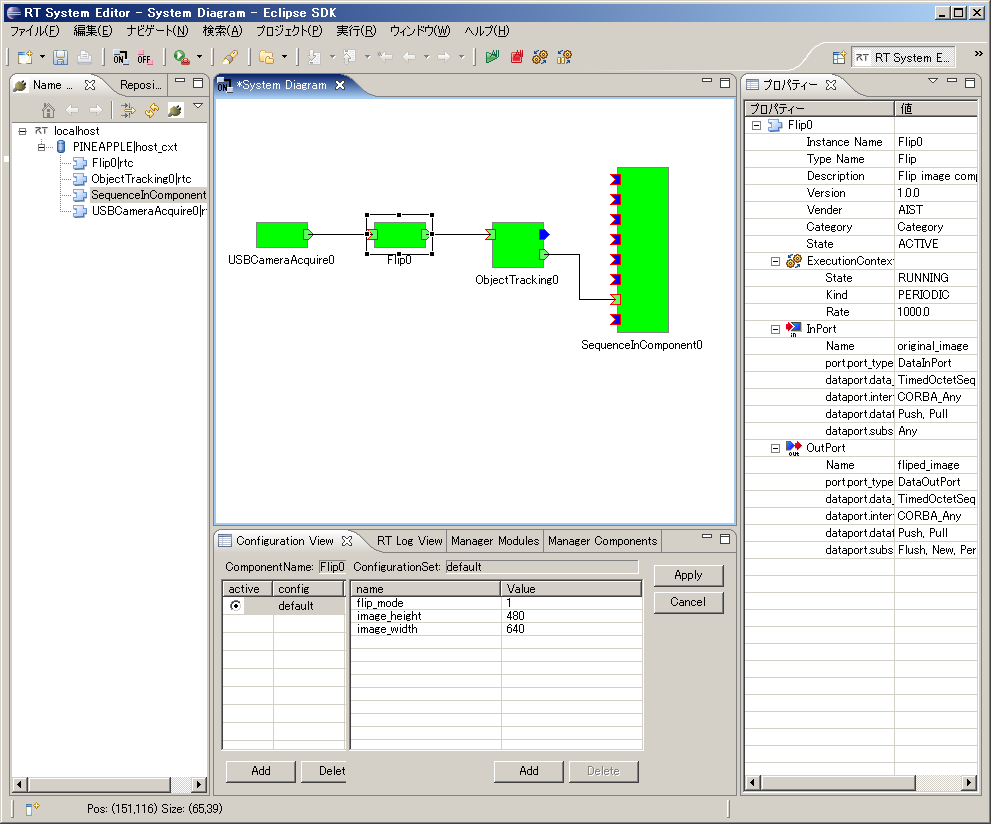
ObjectTrackingコンポーネントのビルド済みパッケージ
ビルド済みパッケージを下記からダウンロードできます。
拡張子を"zip_"としてますので、"zip"にリネームしてから解凍して下さい。
Development of RT Component (NXTway case)
はじめに
- NXT MINDSTORM と OpenRTM の Bluetooth コンポーネントと接続し、NXT MINDSTORM をコントロールする方法を説明する。
- NXT MINDSTORM に対するソフトウェアのインストール方法および基本的な操作、RTコンポーネントとの接続する方法を説明する。
環境構築
LEGO の組み立て
- 必要な部品
- LEGO MINDSTORMS Education NXT Base Set
- Product ID: W979797
- LEGO Education Resource Set
- Product ID: W979648
- NXT Gyro Sensor
- Part No : NGY1044
- LEGO MINDSTORMS Education NXT Base Set
- LEGOの組み立て方法
- 「NXTway-GS_Building_Instructions.pdf」参照すること
- Download : http://lejos-osek.sourceforge.net/NXTway-GS_Building_Instructions.pdf
nxtOSEK 環境設定(Windows XP/Vista)
- Cygwin のインストール
- Cygwin は Windows 環境で各種の Linux ソフトウェアを実行できることである
- Download : http://www.cygwin.com/
- 設定オプション
- Root Directory : 「c:\cygwin」
- Select Packages : Devel カテゴリにある「make 3.81-1」と Libs カテゴリにある「libintl3」を選択してインストールする
- GNU ARM のインストール(必ず4.0.2)
- GNU ARM は NXT の ARM7コアプロセッサ(AT91SAM7S256)に対応した GCC コンパイラパッケージである
- Download : http://www.gnuarm.com/bu-2.16.1_gcc-4.0.2-c-c++_nl-1.14.0_gi-6.4.exe
- 設定オプション
- Diriectory : 「c:\cygwin\GNUARM」
- Select Components : 「Floating Point Unit」選択しない
- Select Additional Tasks : 「Install Cygwin DLLs...」選択しない
- LEGO MINDSTORMS NXT Drive rのインストール
- LEGO 社から提供される NXT とのUSB 通信ドライバーである
- Download : http://mindstorms.lego.com/en-us/support/files/Driver.aspx
- Driver 1.02 の PC バージョンをインストールする
- NeXTTool のダウンロード
- NeXTTool は NXTと通信用 PC コンソールで、*.rxe(アプリ) と *.rfw(ファームウェア)を NXT にアップできる
- Download : http://bricxcc.sourceforge.net/nexttool.zip
- 設定オプション
- 解凍ディレクトリ : 「c:\cygwin\nexttool」
- 拡張 NXT ファームウェアのダウンロード
- 拡張 NXT ファームウェアは標準 NXT ファームウェアをベースに機能拡張したものである
- NXT の ARM7 コアCPUのネイティブコードも実行できる
- Download : http://bricxcc.sourceforge.net/lms_arm_jch.zip
- 設定オプション
- 「lms_arm_nbcnxc_107.rfw」だけをコピーする
- コピーディレクトリー : 「c:\cygwin\nexttool」
- nxtOSEK のダウンロード
- バージョン2.13 をダウンロードする
- Download : http://sourceforge.net/projects/lejos-osek/files/nxtOSEK/
- 設定オプション
- 解凍ディレクトリ : 「c:\cygwin\nxtOSEK」
- 「sg.exe」ファイル追加
- Download : http://www.toppers.jp/download.cgi/osek_os-1.1.lzh
- 解凍して「toppers_osek」フォルダーの下に「sg」フォルダーの下にある「sg.exe」ファイルを「c:\cygwin\nxtOSEK\toppers_osek\sg」フォルダーにコピーする
拡張 NXT ファームウェアの NXT へのアップロード
- NXT ファームウェアアップデートモード
- 電流が ON の状態でリセットボタンを安全ピンの先で5秒ぐらい押し続ける
- NXT スピーカーに小さなクリック音が聞こえるようになる
- NXT と PC の USB 接続
- Cygwin 起動及び拡張ファームウェアアップロード
 cygwinを起動する
- 下記のコマンドを入力
$cd c:\cygwin\nexttool $./NeXTTool.exe /COM=usb -firmware=lms_arm_nbcnxc_107.rfw
- アップロードが完了すると、NXT の液晶画面が砂嵐画面のようになる
- NXT のボタン操作できない場合は NXT のバッテリを外し再び装着することで拡張 NXT ファームウェアが起動
- 下記のコマンドを入力
NXTway ソース修正及びコンパイル
NXT 側のソース修正及びコンパイル、アップロード
- ソース修正
- 「c:\cygwin\nxtOSEK\samples_c++\cpp\NXTway_GS++」フォルダーにある「sample.cpp」の中で
- 「btConnection.connect」で検索したら、下記の「Main Task」の中にある関数が検索できる
//============================================================================= // Main Task TASK(TaskMain) { // establish blutooth connection with a PC to use a PC HID GamePad controller BTConnection btConnection(bt, lcd, nxt); (void)btConnection.connect(BT_PASS_KEY); for (U32 i = 5; i <= Lcd::MAX_CURSOR_Y; i++) lcd.clearRow(i); lcd.cursor(0,5); lcd.putf("snsns", "TOUCH:START/STOP", "STAND IT UP AND", "WAIT FOR A BEEP."); lcd.disp(); SetRelAlarm(Alarm4msec, 1, 4); // Set 4msec periodical Alarm for the drive event while(1) { sonarDriver.checkObstacles(sonar); clock.wait(40); // 40msec wait } } - 「(void)btConnection.connect(BT_PASS_KEY);」を下記のように修正する
(void)btConnection.connect(BT_PASS_KEY, "alias")
- "alias"の部分に自分が確認できる名前を入力する
- コンパイル
 cygwinを起動する
 $cd c:\cygwin\nxtOSEK\samples_c++\cpp\NXTway_GS++
- cygwinの上で上のフォルダ「C:\cygwin\nxtOSEK\samples_c++\cpp\NXTway_GS++」で
$make all ... Generating binary image file: nxtway_gs++_rom.bin Generating binary image file: nxtway_gs++_ram.bin Generating binary image file: nxtway_gs++_.rxe $
- 上のようなメッセージを確認すればコンパイル完了
- NXT にアップロード
- 拡張 NXT ファームウェアが入っている NXT を USB で接続する
- コンパイルした cygwin の状態で
$sh ./rxeflash.sh Executing NeXTTool to upload nxtway_gs++.rxe... nxtway_gs++.rxe=34240 NeXTTool is terminated. $
- 上のようなメッセージを確認したらアップロード完了
動作確認
NXT側の起動
- 下の図で⑦番の状態で待機する;
PC 側 RTC の起動
- OpenRTM-aist の Naming Service をスタートする
- TkJoyStickComp コンポーネントを起動する
- Bluetooth 接続
- Bluetooth を PC に接続する
- "alias"の部分で入れたネームの Bluetooth ディバイスを接続する
- Password は基本的に「1234」に設定されている
- 接続した Bluetooth の Comport を確認する
- Bluetooth コンポーネントを起動
- BluetoothComp.zipをダウンロード
- BluetoothComp.zipを解凍した後、「components」フォルダーにある「NXTBlueToothComp.exe」ファイルを実行する
- RT System Editor を起動
- 下の図のようにRT System Editor を起動する
- Naming Service 追加
- 下の図のように追加ボタンをクリックし、「127.0.0.1」を追加する
- コンポーネント配置
- 下の図のようにコンポーネントを配置する
- TkJoyStickComp と Bluetooth コンポーネントを接続する
- 下の図のように TkJoyStickComp と BluetoothComp を接続する
- Bluetooth コンポーネントの Configuration View で「m_COM」変数に確認した Comport の番号を入れる
- Activate する
- 接続が完了したら NXT 側が下の図のようになる
LEGO Mindstorm NXT RT component
LEGO Mindstorms NXT RT-Component
LEGO Mindstorms NXT is a collection of LEGO components for creating robots. It includes 3 motors, 4 types of sensor and an intelligent brick, the NXT brick, for connecting and controlling them. NXT is connected via USB or Bluetooth to a PC, from which it can be directly controlled and programmed. It can also be loaded with user-created programs for operation independent of a PC.
This article will describe how to create an RT-Component (RTC) for the intelligent brick on a PC and, using other components, control connected motors and read connected sensors. With a single component for the NXT brick, controlling motors and reading sensors using existing RT-Components is simple.
Preparing SD Card
はじめに
ここでは、LEGO Mindstorms EV3 上で OpenRTM-aist とそのコンポーネントを動作させるための実行環境のインストールについて説明します。
ここでは、openrtm.org が提供する OpenRTM-aist 入りの OSイメージをダウンロードし、各種セットアップについて説明します。 EV3上で OpenRTM を使用できるようにするまでの大まかな手順は以下の通りです。
- SDカードに OSイメージを書き込む
- OS の基本的なセットアップ
- コンポーネントの実行テスト
SD カード
EV3 には micro SD カードスロットが一つあり、ここに起動した OS を書き込んだ micro SD カードを差し込むと、任意の OS を起動することができます。
用意する SDカードは 2GB以上 32GB以下のも micro SDカード になります。mini SD や SDカードは刺さりませんのでご注意ください。 また、書き込むイメージは約2GB程度ありますので、最低で2GBの容量が必要となります。EV3 は 32GBより大きい SDXC仕様の SDカードには対応していませんので、注意してください。
- 用意するSDカード
- micro SDカード
- 2GB以上、32GB以下
OSイメージのダウンロード
EV3上 での OpenRTM-aist の実行には ev3dev という OS を使用します。
- ev3dev Webページ: http://www.ev3dev.org
以下のサイトから ev3-ev3dev-jessie-2015-12-30.img.zip をダウンロードしてください。 名前が似たファイルが多数配布されているので間違えないようにしてください。
ev3dev OSイメージのダウンロード
ev3dev とは EV3 上で Linux のディストリビューションの1つである、Debian GNU Linuxを EV3 に搭載した EV3用の Debian ディストリビューションです。 OpenRTM-aist を動作させるには、この ev3dev を micro SDカードに書き込み、EV3 を SDカードから起動させます。
上記の ev3dev オフィシャルWebページから ev3dev の OSイメージファイルがダウンロードできますが、OpenRTM-aist などはインストールされていません。 基本的には、以下のリンクから OpenRTM-aist (C++、Python) 入りの ev3dev イメージファイルをダウンロードしてください。
サンプルコンポーネント入りのイメージ
Educator Vehicle等のサンプルコンポーネント入りのイメージです。
EV3の無線LANアダプタを交換した場合に、無線LANアクセスポイントモードが正常に動作しない場合があります。 その場合は他のアクセスポイントに接続する等して、以下のコマンドを実行して70-persistent-net.rulesを編集します。 ユーザー名はrobot、パスワードはmakerでログインして操作してください。
sudo nano /etc/udev/rules.d/70-persistent-net.rules
具体的には70-persistent-net.rulesのSUBSYSTEMから始まる行を全てコメントアウトします。
# USB device 0x:0x (rtl8192cu)
SUBSYSTEM=="net", ACTION=="add", DRIVERS=="?*", ATTR{address}=="00:22:cf:f6:52:a5", ATTR{dev_id}=="0x0", ATTR{type}=="1", KERNEL=="wlan*", NAME="wlan1"イメージの展開
ダウンロードしたファイル YYYY-MM-DD-ev3dev-openrtm.zip を展開してください。 YYYY-MM-DD-ev3dev-openrtm.img という2GB位のファイルが展開されているはずです。
Windows
ファイルを右クリックして「すべて展開」を選択すると、展開できます。
Linux
$ unzip <イメージファイル>
で展開できます。unzip コマンドがない場合はインストールしてください。
$ unzip 2015-08-06-ev3dev-openrtm.zip Archive: 2015-08-06-ev3dev-openrtm.zip inflating: 2015-08-06-ev3dev-openrtm.img $ ls -l 合計 2321300 -rw-rw-r-- 1 n-ando n-ando 1887436800 8月 4 21:37 2015-08-06-ev3dev-openrtm.img -rw-rw-r-- 1 n-ando n-ando 489565916 8月 5 10:13 2015-08-06-ev3dev-openrtm.zip
うまく展開できない場合、ダウンロードに失敗しファイルが壊れている可能性があります。壊れたファイルを削除して、再度ダウンロードしてみてください。
イメージの書き込み
展開された yyyy-mm-dd-ev3dev-openrtm.img はイメージファイルといい、ev3dev が起動するディスクの状態をディスクの最初から最後まで1バイトづつ抜き出したものです。 このファイルを SDカードに単純にコピーしても使用することはできません!!
以下に説明する方法で SDカードに書き込んでください。
イメージの書き込み (Windows)
Windows では Win32DiskImager というツールを使用することでイメージの書き込みができます。 以下のサイトからイメージデータ書き込みツール Win32DiskImager のバイナリをダウンロードします。
- Win32DiskImager: http://sourceforge.jp/projects/sfnet_win32diskimager/ Win32DiskImager のダウンロード
ダウンロードしたファイル (win32diskimager-vX.X-binary.zip ) を解凍します。
※Win32DiskImager は、2バイト文字に対応していないため、YYYY-MM-DD-ev3dev-openrtm.zip は途中のパス名に全角文字や空白が含まれていない場所に解凍してください。
Raspberry Pi で使用する SD カードを PCに挿入し、Win32DiskImager を起動します。
※SD カードはドライブとして認識されている必要があるので、事前に FAT32 形式でフォーマットしておいてください。
「Image File」に解凍したRaspbian のイメージファイル (YYYY-MM-DD-wheezy-raspbian.img)、「Drive」にSD カードのドライブを指定し、「Write」ボタンをクリックします。
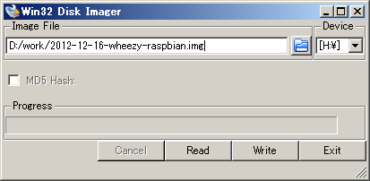
以上で SD カードの準備は終了です。 書き込みが終了したら、SD カードを Raspberry Pi に設置し、電源を投入します。
イメージの書き込み (Linux)
Linux では dd コマンドを利用してイメージの読み書きができます。 dd コマンドは UNIX系の OS なら大抵デフォルトでインストールされています。
SDカードを差し込んでから、 dmesg コマンドでカーネルのメッセージを確認します。
$ dmesg : 中略 [333478.822170] sd 3:0:0:0: [sdb] Assuming drive cache: write through [333478.822174] sdb: sdb1 sdb2 [333478.839563] sd 3:0:0:0: [sdb] Assuming drive cache: write through [333478.839567] sd 3:0:0:0: [sdb] Attached SCSI removable disk [333479.094873] EXT4-fs (sdb2): mounted filesystem with ordered data mode [333527.658195] usb 1-1: USB disconnect, address 2
このメッセージから SDカードのデバイス名を確認します。この例では sdb が SDカードのデバイス名のようです。/dev/の下を見てみます。
ls -al /dev/sd* brw-rw---- 1 root disk 8, 0 May 7 17:28 /dev/sda brw-rw---- 1 root disk 8, 1 May 7 17:28 /dev/sda1 brw-rw---- 1 root disk 8, 2 May 7 17:28 /dev/sda2 brw-rw---- 1 root disk 8, 5 May 7 17:28 /dev/sda5 brw-rw---- 1 root disk 8, 16 May 18 14:19 /dev/sdb brw-rw---- 1 root disk 8, 17 May 18 14:19 /dev/sdb1 brw-rw---- 1 root disk 8, 32 May 18 14:19 /dev/sdc
sda は大抵システムディスクなので、絶対に触ってはいけません。
ディストリビューションによっては、SDカード内にマウント可能なファイルシステムがある場合自動でマウントするケースもあるようです。 その場合、ディスクをアンマウントしてください。(Ubuntuではデスクトップにマウントしたファイルシステムのフォルダーが現れるので右クリックで取り外してください。 それ以外は umount コマンドでアンマウントします。)
dd if=イメージファイル of=SDカードのデバイスファイル bs=1M のようにコマンドを入力し実行します。 ただし、デバイスファイルへの書き込みは管理者(root)権限が必要ですので、sudoを使用してください。
$ sudo dd if=2015-08-05-ev3dev-openrtm.img of=/dev/sdb bs=1M 1850+0 records in 1850+0 records out 1939865600 bytes (1.9 GB) copied, 201.543 s, 9.6 MB/s
実行中は別のターミナルなどで、iostat コマンドを実行して書き込みが正しく行われているかどうか見ることができます。 (最近のディストリビューションではデフォルトでインストールされていないことがあります。debian/ubuntu では apt-get install sysstat で iostatコマンドが使えるようになります。)
$ iostat -mx 1
avg-cpu: %user %nice %system %iowait %steal %idle
0.00 0.00 0.00 50.25 0.00 49.75
Device: rrqm/s wrqm/s r/s w/s rMB/s wMB/s avgrq-sz avgqu-sz await svctm %util
sda 0.00 0.00 0.00 1.00 0.00 0.00 8.00 0.00 0.00 0.00 0.00
sdb 0.00 1856.00 0.00 78.00 0.00 9.14 240.00 143.40 1855.85 12.82 100.00sdb の項目を見ると 9.14MB/s の書き込み速度が出ていることがわかります。 class 6 のSDカードなら 6MB/sec, class 10 の SDカードなら 10MB/sec 程度の速度が出ていれば、問題なく書き込まれていると考えてよいでしょう。 書き込みが終了すると、ディストリビューションによっては自動でマウントされる場合があります。その場合、アンマウントしてから SDカードを抜いてください。
イメージの書き込み (Mac OS X)
Mac OS X も Linuxと同様 dd コマンドを利用して書き込みます。 ただし、Mac では SDカードを挿入すると自動的にマウントされてしまい、マウント中は dd コマンドで SDカードに書き込むことができないので、アンマウント (OSから取り外す) する必要があります。
SDカードを差し込むとFinderに図のように SDカードのアイコンが現れます。 アンマウントするつもりでイジェクトボタンを押さないよう気を付けてください。
SDカードのボリューム名はここでは Untitled です。ボリューム名を覚えておきます。 コマンドプロンプトから df コマンドを入力すると以下のように表示されます。
$ df -k Filesystem 1024-blocks Used Available Capacity iused ifree %iused Mounted on /dev/disk0s2 500000000 437664508 62079492 88% 109480125 15519873 88% / devfs 194 194 0 100% 679 0 100% /dev map -hosts 0 0 0 100% 0 0 100% /net map auto_home 0 0 0 100% 0 0 100% /home /dev/disk1s1 57288 18992 38296 34% 512 0 100% /Volumes/Untitled
一番下 ''/Volumes/Untitled'' とあるのが先ほどの SDカードのマウントポイントです。一番左の SDカードのデバイス名 /dev/disk1s1 を覚えておきます。
$ diskutil umount /Volumes/Untitled Volume (null) on disk1s1 unmounted $ df -k Filesystem 1024-blocks Used Available Capacity iused ifree %iused Mounted on /dev/disk0s2 500000000 437664716 62079284 88% 109480177 15519821 88% / devfs 194 194 0 100% 679 0 100% /dev map -hosts 0 0 0 100% 0 0 100% /net map auto_home 0 0 0 100% 0 0 100% /home
先ほどの /Volumes/Untitled が消えて、SDカードがアンマウントされていることがわかります。 次に dd コマンドを使用してイメージを書き込みます。 dd if=イメージファイル of=/dev/rdisk1 bs=1m のように入力します。 of=/dev/rdisk1 は先ほど覚えたデバイスファイル /dev/disk1s1 のうち後ろの s1 を取り、さらに disk の前に raw deviceであることを示す r を付けたデバイス名です。
このコマンドはデバイスファイルにアクセスするので管理者 (root) でなければ実行できません。sudoを使用して以下のように実行します。
$ sudo dd if=2015-08-05-ev3dev-openrtm.img of=/dev/rdisk1 bs=1m 1850+0 records in 1850+0 records out 1939865600 bytes transferred in 302.377337 secs (6415380 bytes/sec) $
書き込み中は、「アクティビティモニタ」で「ディスクの動作」を見ることで書き込みが正しく行われているかどうかわかります。 class 6 の SDカードなら 6MB/sec, class 10のSDカードなら 10MB/sec 程度の速度が出ていれば、問題なく書き込まれていると考えてよいでしょう。
書き込みが終了すると、自動的に再度マウントされますので、今度は Finder のイジェクトボタンを押して SDカードを抜きます。
Mindstorms NXT Setup
Mindstorms NXT Setup
To create an RTC for the NXT, you must first setup your PC and NXT. The NXT can be connected to the PC by USB or Bluetooth, but because we don't want to tie our battery-powered, portable NXT to the PC with a cable, we will use Bluetooth.
Block assembly
Using the assembled robot shown in the photo as an example, we will create the NXT RTC.
This is a simple mobile base, called "Tribot," combined with a ultrasonic sensor (the "eyes") at the front. The Tribot construction instructions can be found in the NXT "Start Here" booklet included in the NXT kit. Attach the ultrasonic sensor to this base.
Bluetooth Device Installation
All revisions of the NXT intelligent brick include Bluetooth support. PCs without Bluetooth included can use USB Bluetooth adapters like those shown in the photo to communicate with the NXT. Install such a device if necessary, including any required device drivers. Most versions of Windows from XP SP2 on include suitable default device drivers.
Once a Bluetooth device has been installed, a "Bluetooth Devices" item should appear in the control panel. Clicking on this will produce the dialog shown below.
Select "Options," and enable device discovery and displaying the Bluetooth icon in the notification area. We will connect the NXT to the PC next, so leave this dialog open.
Connecting the NXT to the PC
The process to connect the NXT to the PC via Bluetooth is given below.
- Turn on the NXT
- Put the NXT into Bluetooth search mode
- Select your PC
- Select a channel
- Start the Connection Wizard from the Bluetooth Devices dialog on the PC
- Set a pass key
- Push the connect button on both the PC and NXT
- Restart the NXT once it has connected.
Starting the NXT
Press the central orange button on the NXT to turn on the power. A sequence of beeps will sound (if the volume is not set to zero) and the brick will turn on. The screen should look like the image below.
If it does not, use the square button below the orange button to navigate to the "My Files" mode.
Bluetooth Device Search
In "My Files" mode, press the triangular, grey buttons on either side of the orange button to move the cursor to the "Bluetooth" option, and press the orange button.
Use the grey buttons again to move the cursor to the "Search" option.
Press the orange button and a search for Bluetooth devices will be conducted. The screen will appear as below while searching.
Device Connection
If the PC has Bluetooth enabled and is visible to the NXT, the PC's name (as set in Windows) should appear on the screen of the NXT.
If other Bluetooth-enabled PCs are nearby, you may see more than one appear on the NXT. Use the triangular buttons to move the cursor to the correct PC name, then press the orange button. The channel selection screen will appear next. Press the orange button on the default selection. After displaying "Connecting" for a short time, the pass key input screen will appear. Press the orange button.
An information balloon should appear on the PC. Click on it to close it.
If the PC asks for a pass key, input the key that was displayed on the NXT. Once a connection is established, a dialog like that shown below will appear. To prevent other devices interfering, check "Disable discovery" before clicking "Finish."
Connection confirmation
Click on the "Devices" tab in the Bluetooth Devices dialog. The NXT should appear as below.
Installing NXT Python
Installing PyBlues
Download the Windows installer from the above link and run it.
Installing NXT Python
Download the zip file from the above link. NXT Python uses a setup.py script to install. If you have associated .py files with the Python interpreter, execute the script as follows from a command prompt:
setup.py install
c:\Python24\python setup.py install
Microsoft Windows XP [Version 5.1.2600] (C) Copyright 1985-2001 Microsoft Corp. C:\tmp\nxt_python-0.7>setup.py install running install running build running build_py ... copying build\scripts-2.4\nxt_filer -> c:\python24\Scripts copying build\scripts-2.4\nxt_push -> c:\python24\Scripts copying build\scripts-2.4\nxt_test -> c:\python24\Scripts C:\tmp\nxt_python-0.7>
Test NXT Python
Turn on the NXT and connect it to the PC. Using the samples under example/, confirm that the NXT can be controlled from the PC.
The example/ directory contains the following samples:
- latency.py: Measures the latency in reading the sensors.
- mary.py: Plays "Mary Had a Little Lamb."
- message_test.py: Displays a message on the NXT's screen.
- spin.py: Spins motors connected to ports B and C.
- test_sensors.py: Displays all sensor values.
Motors and sensors must be connected appropriately for each test.
Making a NXT Python RTC
After completing the above preparations, the NXT should be controllable from the PC using Python.
At this point, you could use RtcTemplate to generate a NXT component template and get stuck in coding. However, while NXT Python is a clean module, please read on a little before putting NXT Python directly into an RT-Component.
As you can see from the samples, NXT Python is organised into modules for locators, motors, sensors, etc. In order to provide fine control over motors and sensors, the access method is a little complex.
We will create a class that allows us to access the many NXT Python modules through a single interface. We will use the Facade software pattern.
The facade pattern is a software engineering design pattern commonly used with Object-oriented programming. A facade is an object that provides a simplified interface to a larger body of code, such as a class library. (Source: "Facade pattern," Wikipedia)
Making such a class has the following benefits:
- Use it in places other than the RTC
- Easier to debug
- Debug the facade in isolation
- Debugging directly in the RTC makes it difficult to determine if a problem is because of the facade or the RTC.
- Modifications are easier
- Even if the facade class changes, if the interface does not change then the RTC component does not need to be changed.
- For example, if you want to add limits to some functions called get_xxx() and set_xxx(), this will only require changes in the facade.
- Easier to use devices other than the NXT
- For example, switching to a new version of the NXT that uses the same interface.
This is generally the case for RT-Components. Make good classes for robots and devices you wish to interact with, and even if the RTC itself changes or a new version is made, it will be easy to interact and maintenance will be greatly simplified.
Avoid creating low-level code like the following in your RTC's onExecute() method:
ioctl(xxxx, xxxx); // UNIX direct device access inb(xxx); // Direct I/O outb(xxx); // Direct I/O
Ideally, create code like the following:
onExecute(ec_id) { // Pseudocode
if (m_inport.isNew()) {
retval = m_myrobot.set_actuator(m_inport.read());
if (retval == fatal_error) return RTC::RTC_ERROR;
}
if (myrobot.get_sensor(sensor_data) == true) {
m_outport.write(sensor_data);
} else {
// Processing a read error
if (fatal_error) return RTC::RTC_ERROR;
}
return RTC::RTC_OK;
}Code like this calls a function to process data from the input port and write sensor data to the output port. This sort of abstract code is ideal.
NXT Python Facade Class
NXT Python Facade Class
Nearly all functions of the NXT brick can be controlled using NXT Python. However, because utilising all functions is complex, the facade class will only focus on those functions we want to use. The main functions of the NXT are:
- Input
- Set motor speed
- Control the speaker
- Display messages
- Output
- Read motor encoder values
- Read sensors (microphone, ultrasonic, touch, light)
- Read system information
- Other
- Search for a NXT
- Connect to a NXT
- Read files from the NXT
- Read the NXT firmware
There is little meaning to putting all of these functions into the facade class. When another function is necessary, the facade can be extended to include it. In keeping with this, the facade described here will supply the functions necessary for the robot we will control.
- Input
- Set motor speed: setMotors()
- Output
- Read motor encoders: getMotors()
- Read sensors (microphone, ultrasonic, touch, light): getSensors()
A class made along these lines is shown below.
#!/usr/bin/env python
# @file NXTBrick.py
# -*- coding:shift_jis -*-
import nxt.locator
from nxt.sensor import *
from nxt.motor import *
class NXTBrick:
def __init__(self, bsock=None):
"""
Constructor
Connect to a NXT brick, control motors and sensors, and reset odometry.
"""
if bsock:
self.sock = bsock
else:
self.sock = nxt.locator.find_one_brick().connect()
self.motors = [Motor(self.sock, PORT_A),
Motor(self.sock, PORT_B),
Motor(self.sock, PORT_C)]
self.sensors = [TouchSensor(self.sock, PORT_1),
SoundSensor(self.sock, PORT_2),
LightSensor(self.sock, PORT_3),
UltrasonicSensor(self.sock, PORT_4)]
self.resetPosition()
def close(self):
"""
Close the connection to the NXT.
"""
self.sock.close()
def resetPosition(self, relative = 0):
"""
Reset the NXT motor encoders.
"""
for m in self.motors:
m.reset_position(relative)
def setMotors(self, vels):
"""
Receive an array, set the motor power levels.
If the length of vels is not equal to the number of motors,
the smaller of the two values is used.
"""
for i, v in enumerate(vels[:min(len(vels),len(self.motors))]):
self.motors[i].power = max(min(v,127),-127)
self.motors[i].mode = MODE_MOTOR_ON | MODE_REGULATED
self.motors[i].regulation_mode = REGULATION_MOTOR_SYNC
self.motors[i].run_state = RUN_STATE_RUNNING
self.motors[i].tacho_limit = 0
self.motors[i].set_output_state()
def getMotors(self):
"""
Read the motor encoder angles.
"""
state = []
for m in self.motors:
state.append(m.get_output_state())
return state
def getSensors(self):
"""
Read the sensor values, return them in an array.
"""
state = []
for s in self.sensors:
state.append(s.get_sample())
return state
"""
Test program
Set a suitable motor value, read their encoders.
Read sensor values and display them.
"""
if __name__ == "__main__":
import time
nxt = NXTBrick()
print "connected"
# Motor test
for i in range(100):
nxt.setMotors([80,-80,80])
print "Motor: "
mstat = nxt.getMotors()
for i, m in enumerate(mstat):
print "(" , i, "): ", m
time.sleep(0.1)
nxt.setMotors([0,0,0])
# Sensor test
for i in range(100):
sensors = ["Touch", "Sound", "Light", "USonic"]
sval = nxt.getSensors()
for s in sensors:
print s + ": " + sval
print ""
time.speel(0.1)The final section from if name == "main": is a test program. When this module is executed independently, the test will run. The module should be tested and corrected until it passes the test succesfully.
The above NXT facade class is very simple, only setting motor values, reading the encoders and reading the sensors. Trying to do everything from the start leads to a class whose purpose is difficult to understand. The class can be extended at any time, so begin with something simple that works as it should.
NXT RTC Implementation
NXT RTC Implementation
We shall now use the NXTBrick class created above to create an RTC.
- InPort
- Motor speed (TimedFloatSeq)
- Outport
- Motor position (TimedFloatSeq)
- Sensor data (TimedFloatSeq)
Generate NXTRTC base code
Generate the NXT RTC template
We shall use RtcTemplate to generate a template component. You can use the command line tool, rtc-template, or the Eclipse-based tool, RtcTemplate, to create the component.
If using rtc-template, make a batch file containing the following (remember to adjust paths as necessary):
python "C:\Program Files\OpenRTM-aist\0.4\utils\rtc-template\rtc-template.py" -bpython^ --module-name=NXTRTC --module-desc="NXT sample component"^ --module-version=0.1 --module-vendor=AIST --module-category=example^ --module-comp-type=DataFlowComponent --module-act-type=SPORADIC^ --module-max-inst=10^ --inport=vel:TimedFloatSeq^ --outport=pos:TimedFloatSeq --outport=sens:TimedFloatSeq^ --config="map:string:A,B"
Executing rtc-template using a created gen.bat:
> gen.bat python "C:\Program Files\OpenRTM-aist\0.4\utils\rtc-template\rtc-template.py" -bpython --module-name=NXTRTC --module-desc="NXT sample component" --module-version=0.1 --module-vendor=AIST --module-category=example --module-comp-type=DataFlowComponent --module-act-type=SPORADIC --module-max-inst=10 --inport=vel:TimedFloatSeq --outport=pos:TimedFloatSeq --outport=sens:TimedFloatSeq --config="map:string:A,B" File "NXTRTC.py" was generated. File "README.NXTRTC" was generated. File "NXTRTC.yaml" was generated.
- Programing language selection: Python
- Module definition
- Module name: NXTRTC
- Module decription: NXT sample component
- Module version: 0.1
- Module vender: AIST
- Module category: example
- Component type: DataFlowComponent
- Component's activity type: SPORADIC
- Number of maximum instance: 10
- InPort definition
- Ports: Name:vel Type:TimedFloatSeq
- OutPort definition
- Ports: Name:pos, Type:TimedFloatSeq
- Ports: Name:sens, Type:TimedFloatSeq
- ConfigurationSet definition
- Cfg Sets: Name:map, Type:string, Default Value: A,B
Following these instructions should create the NXTRTC.py file containing the template component.
Sample code explanation
Sample code explanation
We will now add the NXTBrick.py functionality to the generated component.
- NXTBrick.py import: Import the NXTBrick.py file to get access to the NXTBrick class. The file extension is not necessary in the import statement.
import NXTBrick
- Implement onInitialize(self): In onInitialize(), instantiate the NXTBrick class. If this causes an error, return RTC_ERROR and the component will transition to the end state.
# create NXTBrick object try: self._nxtbrick = NXTBrick.NXTBrick() except: print "NXTBrick create failed.""" return RTC.RTC_ERROR
- Implement onActivated(self, ec_id) and onDeactivated(self, ec_id): In onActivated() and onDeactivated(), the NXTBrick class's resetPosition() method should be called.
self._nxtbrick.resetPosition()
- Implement onExecute(self, ec_id): The following steps should be performed by onExecute():
- Read speeds from the data InPort
- Based on configuration values, which port of the NXT the speed values are to be sent to should be set.
- Call the setMotors() method of the NXTBrick class to set motor speeds.
- Call the getSensors() method of the NXTBrick class to read the ultrasonic sensor data, and write this to an OutPort.
- Call the getMotors() method of the NXTBrick class to get the motor encoder angles, and write this to an OutPort.
Code that implements the above functionality is shown below:
#!/usr/bin/env python
# -*- coding:shift_jis -*-
# -*- Python -*-
import sys
import time
sys.path.append(".")
# Import RTM module
import OpenRTM
import RTC
# import NXTBrick class
import NXTBrick
# This module's spesification
# <rtc-template block="module_spec">
nxtrtc_spec = ["implementation_id", "NXTRTC",
"type_name", "NXTRTC",
"description", "NXT sample component",
"version", "0.1",
"vendor", "AIST",
"category", "example",
"activity_type", "DataFlowComponent",
"max_instance", "10",
"language", "Python",
"lang_type", "SCRIPT",
"conf.default.map", "A,B",
""]
# </rtc-template>
class NXTRTC(OpenRTM.DataFlowComponentBase):
def __init__(self, manager):
OpenRTM.DataFlowComponentBase.__init__(self, manager)
# DataPorts initialization
# <rtc-template block="data_ports">
self._d_vel = RTC.TimedFloatSeq(RTC.Time(0,0),[])
self._velIn = OpenRTM.InPort("vel", self._d_vel, OpenRTM.RingBuffer(8))
self.registerInPort("vel",self._velIn)
self._d_pos = RTC.TimedFloatSeq(RTC.Time(0,0),[])
self._posOut = OpenRTM.OutPort("pos", self._d_pos, OpenRTM.RingBuffer(8))
self.registerOutPort("pos",self._posOut)
self._d_sens = RTC.TimedFloatSeq(RTC.Time(0,0),[])
self._sensOut = OpenRTM.OutPort("sens", self._d_sens, OpenRTM.RingBuffer(8))
self.registerOutPort("sens",self._sensOut)
# initialize of configuration-data.
# <rtc-template block="configurations">
self._map = [['A', 'B']]
self._nxtbrick = None
self._mapping = {'A':0,'B':1,'C':2}
def onInitialize(self):
# Bind variables and configuration variable
# <rtc-template block="bind_config">
self.bindParameter("map", self._map, "A,B")
# create NXTBrick object
try:
print "Connecting to NXT brick ...."
self._nxtbrick = NXTBrick.NXTBrick()
print "Connection established."
except:
print "NXTBrick connection failed."
return RTC.RTC_ERROR
return RTC.RTC_OK
def onFinalize(self):
self._nxtbrick.close()
def onActivated(self, ec_id):
# reset NXTBrick's position.
self._nxtbrick.resetPosition()
return RTC.RTC_OK
def onDeactivated(self, ec_id):
# reset NXTBrick's position.
self._nxtbrick.resetPosition()
return RTC.RTC_OK
def onExecute(self, ec_id):
cnt = 0
# check new data.
if self._velIn.isNew():
# read velocity data from inport.
self._d_vel = self._velIn.read()
vel_ = [0,0,0]
vel_[self._mapping[self._map[0][0]]] = self._d_vel.data[0]
vel_[self._mapping[self._map[0][1]]] = self._d_vel.data[1]
# set velocity
self._nxtbrick.setMotors(vel_)
# get sensor data.
sensor_ = self._nxtbrick.getSensors()
if sensor_:
self._d_sens.data = sensor_
self._sensOut.write()
# get position data.
position_ = self._nxtbrick.getMotors()
if position_:
self._d_pos.data = [position_[self._mapping[self._map[0][0]]][9], position_[self._mapping[self._map[0][1]]][9]]
# write position data to outport.
self._posOut.write()
return RTC.RTC_OK
def MyModuleInit(manager):
profile = OpenRTM.Properties(defaults_str=nxtrtc_spec)
manager.registerFactory(profile,
NXTRTC,
OpenRTM.Delete)
# Create a component
comp = manager.createComponent("NXTRTC")
def main():
mgr = OpenRTM.Manager.init(len(sys.argv), sys.argv)
#mgr = OpenRTM.Manager.init(sys.argv)
mgr.setModuleInitProc(MyModuleInit)
mgr.activateManager()
mgr.runManager()
if __name__ == "__main__":
main()Sample code explanation (Callback object usage example)
This sample code adds a callback, OnWrite, to the above sample. When data is written to the InPort's buffer, the motor's speeds will be set immediately.
- Callback class
Create a callback class as below.
# @class CallBackClass
# @brief callback class
#
# when data is written in the buffer of InPort,
# it is called.
class CallBackClass:
def __init__(self, nxtbrick_, map_):
self._nxtbrick = nxtbrick_
self._map = map_
self._mapping = {'A':0,'B':1,'C':2}
def __call__(self, pData):
vel_ = [0,0,0]
vel_[self._mapping[self._map[0][0]]] = pData.data[0]
vel_[self._mapping[self._map[0][1]]] = pData.data[1]
# set velocity
self._nxtbrick.setMotors(vel_)This class receives a NXTBrick instance and a configuration parameter map in its constructor.
- Callback class registration
Use the setOnWrite() method to register a CallBackClass instance with the component.
# set callback class self._velIn.setOnWrite(CallBackClass(self._ntxbrick,self._map))
After this call to setOnWrite(), whenever data is written to the InPort, CallBackClass.call() will be called.
Sample code that implements the complete component using a callback class is shown below.
#!/usr/bin/env python
# -*- coding:shift_jis -*-
# -*- Python -*-
import sys
import time
sys.path.append(".")
# Import RTM module
import OpenRTM
import RTC
# import NXTBrick class
import NXTBrick
# This module's spesification
# <rtc-template block="module_spec">
nxtrtc_spec = ["implementation_id", "NXTRTC",
"type_name", "NXTRTC",
"description", "NXT sample component",
"version", "0.1",
"vendor", "AIST",
"category", "example",
"activity_type", "DataFlowComponent",
"max_instance", "10",
"language", "Python",
"lang_type", "SCRIPT",
"conf.default.map", "A,B",
""]
# </rtc-template>
# @class CallBackClass
# @brief callback class
#
# when data is written in the buffer of InPort,
# it is called.
class CallBackClass:
def __init__(self, nxtbrick_, map_):
self._nxtbrick = nxtbrick_
self._map = map_
self._mapping = {'A':0,'B':1,'C':2}
def __call__(self, pData):
vel_ = [0,0,0]
vel_[self._mapping[self._map[0][0]]] = pData.data[0]
vel_[self._mapping[self._map[0][1]]] = pData.data[1]
# set velocity
self._nxtbrick.setMotors(vel_)
class NXTRTC(OpenRTM.DataFlowComponentBase):
def __init__(self, manager):
OpenRTM.DataFlowComponentBase.__init__(self, manager)
# DataPorts initialization
# <rtc-template block="data_ports">
self._d_vel = RTC.TimedFloatSeq(RTC.Time(0,0),[])
self._velIn = OpenRTM.InPort("vel", self._d_vel, OpenRTM.RingBuffer(8))
self.registerInPort("vel",self._velIn)
self._d_pos = RTC.TimedFloatSeq(RTC.Time(0,0),[])
self._posOut = OpenRTM.OutPort("pos", self._d_pos, OpenRTM.RingBuffer(8))
self.registerOutPort("pos",self._posOut)
self._d_sens = RTC.TimedFloatSeq(RTC.Time(0,0),[])
self._sensOut = OpenRTM.OutPort("sens", self._d_sens, OpenRTM.RingBuffer(8))
self.registerOutPort("sens",self._sensOut)
# initialize of configuration-data.
# <rtc-template block="configurations">
self._map = [['A', 'B']]
self._nxtbrick = None
self._mapping = {'A':0,'B':1,'C':2}
def onInitialize(self):
# Bind variables and configuration variable
# <rtc-template block="bind_config">
self.bindParameter("map", self._map, "A,B")
# create NXTBrick object
try:
print "Connecting to NXT brick ...."
self._nxtbrick = NXTBrick.NXTBrick()
print "Connection established."
except:
print "NXTBrick connection failed."
return RTC.RTC_ERROR
# set callback class
self._velIn.setOnWrite(CallBackClass(self._ntxbrick,self._map))
return RTC.RTC_OK
def onFinalize(self):
self._nxtbrick.close()
def onActivated(self, ec_id):
# reset NXTBrick's position.
self._nxtbrick.resetPosition()
return RTC.RTC_OK
def onDeactivated(self, ec_id):
# reset NXTBrick's position.
self._nxtbrick.resetPosition()
return RTC.RTC_OK
def onExecute(self, ec_id):
# get sensor data.
sensor_ = self._nxtbrick.getSensors()
if sensor_:
self._d_sens.data = [sensor_[3]]
# write sensor data to outport.
self._sensOut.write()
# get position data.
position_ = self._nxtbrick.getMotors()
if position_:
self._d_pos.data = [position_[self._mapping[self._map[0][0]]][9],position_[self._mapping[self._map[0][1]]][9]]
# write position data to outport.
self._posOut.write()
return RTC.RTC_OK
def MyModuleInit(manager):
profile = OpenRTM.Properties(defaults_str=nxtrtc_spec)
manager.registerFactory(profile,
NXTRTC,
OpenRTM.Delete)
# Create a component
comp = manager.createComponent("NXTRTC")
def main():
mgr = OpenRTM.Manager.init(len(sys.argv), sys.argv)
#mgr = OpenRTM.Manager.init(sys.argv)
mgr.setModuleInitProc(MyModuleInit)
mgr.activateManager()
mgr.runManager()
if __name__ == "__main__":
main()
In the first example, the motor output, sensor reading and motor encoder reading are all done in a single synchronous loop. By using a callback, the motor output is done asynchronously when data arrives.
NXT RTC Test
We will now test our NXT RT-Component.
Start the name server
The name server must be started to connect components together. If you have installed the Windows C++ version of OpenRTM-aist, the Start Menu will contain an entry for this: OpenRTM-aist->C++->examples->Start Naming Service.
Write an rtc.conf file
Put the following into a file named "rtc.conf":
 corba.nameservers: localhost
 naming.formats: %n.rtc
- TkJoystickComp
- TkMotorPosComp
- TkSliderMonitorComp
Start RtcLink
Start RtcLink. Once it has started, connect to your name server and open the System Diagram Editor.
Start Components
Execute the following components:- NXTRTC
- TkJoystickComp
- TkMotorPosComp
- TkSliderMonitorComp As each is executed, it will appear in the name service view of RtcLink.
TkJoystickComp
TkJoyStickComp is a graphical virtual joystick component (see image, below). The centre circle can be dragged like a joystick to send X/Y values out its upper OutPort. The lower OutPort outputs values suitable for controlling a differential drive robot, such as the Tribot.
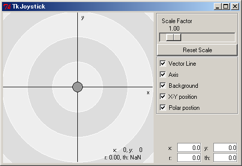
TkMotorComp
TkMotorComp is a GUI-based component for displaying motor angles received at its InPort. It can be used to monitor the rotation of wheels. Connect the angle output port of NXTRTC to its input port to display the angle of the Tribot's wheels. The angle will change even if you turn the wheels by hand.
TkSliderMonitorComp
This component displays values received at its input port in a GUI using sliders. Connect the sensor output of the NXTRTC component to it to monitor the NXT's sensor values.
Connect Components
After executing all components, we will connect them together. Drag each component from the name service view into the system diagram editor window. Click and drag between the ports you want to connect together. The screenshot below shows one example of connecting some components.
Using these components, confirm that the NXTRTC component functions correctly.
Make your own components to control the NXT brick
You have successfully made the NXT into an RT-Component. Now, make new components using your own logic to control the NXT. You can make new components using Python, C++ or Java. No matter what language you use, you can connect your new components with the NXTRTC component created here.

