RTCBuilder-1.1.0
What is RTCBuilder-1.1.0
RTC Builder is one of development tools included in OpenRTM-aist, and it can generate RTC source code model from RTC profile information. C++, Python, Java and other programming languages. In addition, it is created as a plug-in of the Eclipse integrated development environment, and it can operate seamlessly with existing plugins on Eclipse.
Outline/Flow of RTC creation
(G)Operating environment
The environment required for RTCBuilder's operation is as follows.
| № | Environment | Remarks |
| 1 | Java Development Kit 6 | Note: It does not work with Java 1.5 (5.0). |
| 2 | Eclipse 3.4.2 or more http://www.eclipse.org/downloads/index.php http://archive.eclipse.org/eclipse/downloads/index.php |
Eclipse body |
| 3 | Eclipse EMF 2.4以上(SDO, including XSD) | Eclipse plugin on which RTCBuilder depends Please use something that matches the version of Eclipse that will be used. |
| 4 | Eclipse GEF 3.4 or more (Including Draw 2D) | Eclipse plugin on which RTCBuilder depends Please use one that matches the version of Eclipse to be used. |
| 5 | Eclipse Java development tools(JDT) | Please use one that matches the version of Eclipse to be used. |
In addition, it is useful to install the following environment depending on the language in which the following development is performed.
| № | Environment | Remarks |
| 1 | Eclipse CDT | Development environment for C++ |
| 2 | Pydev for Eclipse | Development environment for python |
(G)Flow of RTC creation (C++ language case)
When creating RTC in C++ language, the following tools are required.- By RTCBuilder code generation, you will output the source code template and necessary files for CMake input.
- From the code generated by RTCBuilder, CMake generates a build file (such as Visual Studio solution file and GCC Unix Makefiles) suited to the user's development environment.
- Generate components (dll and so) from build files and source code generated by CMake.
(G)Restriction
RTCBuilder was developed for OpenRTM-aist. We do not expect operation with other RTC platforms.
Installation and start-up
This section explains how to install and start RTCBuilder.
(G)Installing RTCBuilder
RTCBuilder is an Eclipse plugin, so you need to install Eclipse itself and other dependent Eclipse plugins first.
For installation, please refer to OpenRTM Eclipse tools installation.
(G)Starting RTCBuilder
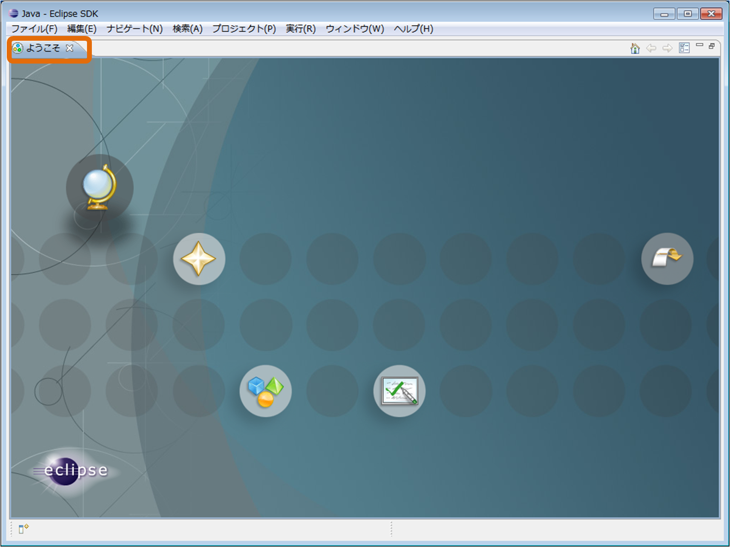
After installing Eclipse for the first time, the following "Welcome" screen will be displayed.
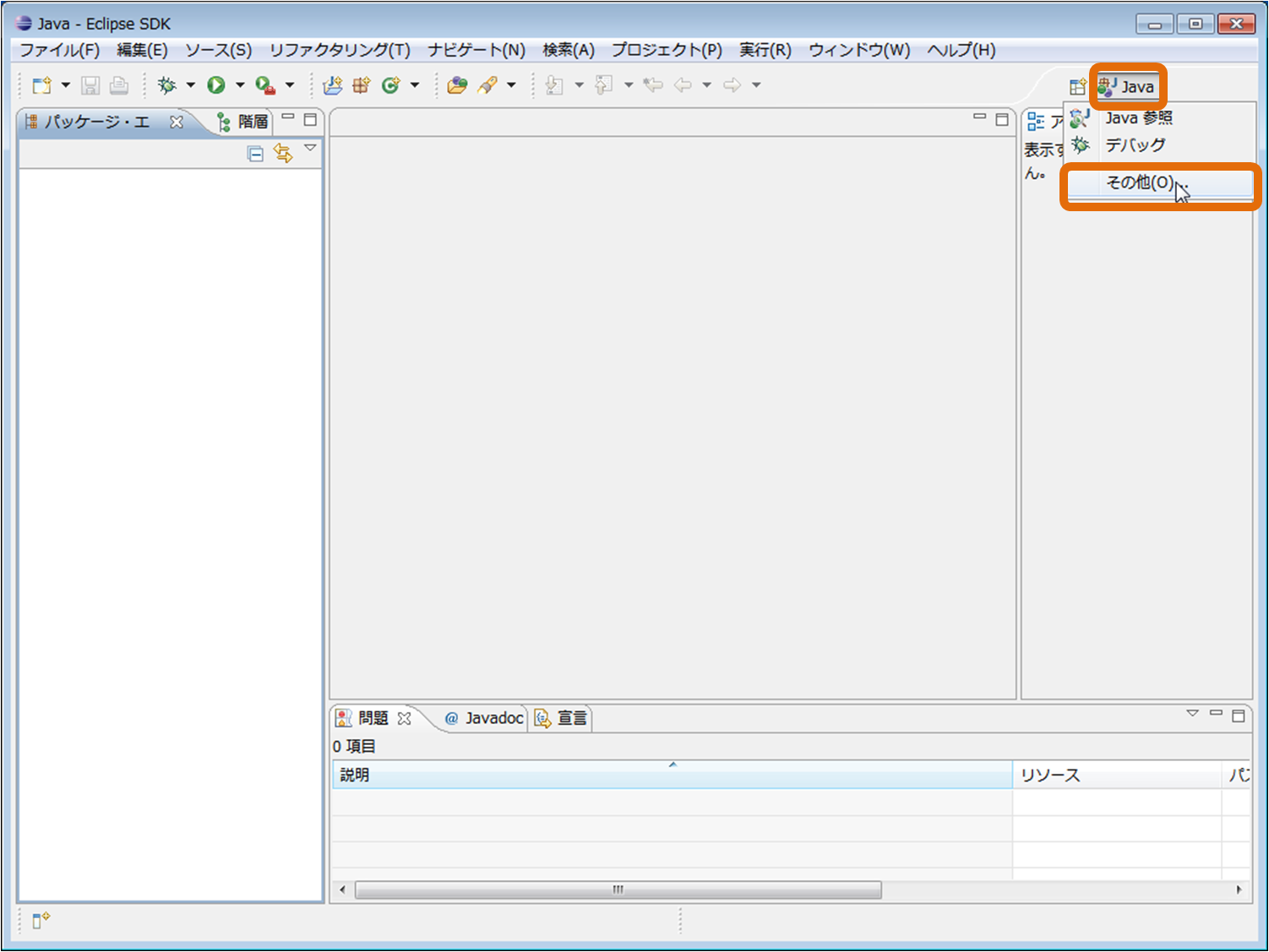
Click the "X" button in the upper left corner of this "Welcome" screen, the following page will be displayed. Click the [Open Perspective] button in the upper right and select "Other" from the pull down.
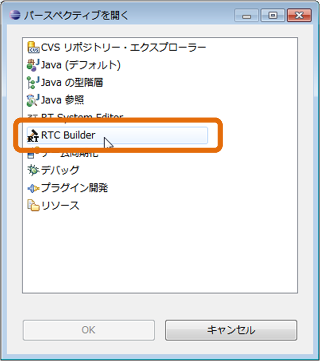
Select "RTC Builder" and click the [OK] button.
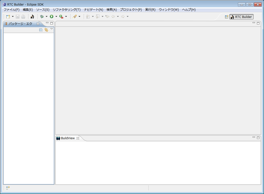
RTCBuilder will start.
(G)Starting the RTC Profile Editor
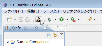
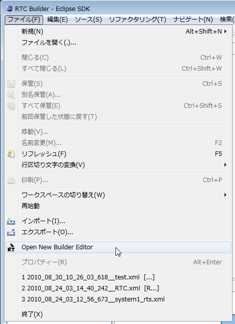
To open the RTC Profile Editor, click the [Open New Rtc Builder Editor] button on the toolbar or select [File] > [Open New Builder Editor] from the menu bar.
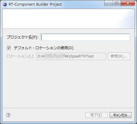
In the new project creation dialog displayed, enter the project name.
Code generated using RTC Builder under the project created here, RTCProfile, etc. are saved. By default, the project is created under the workspace you are using (in the directory set to "location"). If you want to create a project anywhere, turn off the "Use default location" checkbox and specify the location in "Location".
A project with the specified name is generated and added to the package explorer.
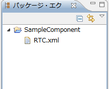
RTC profile XML (RTC.xml) with the default value is automatically generated in the generated project.
Screen structure and functions (overview)
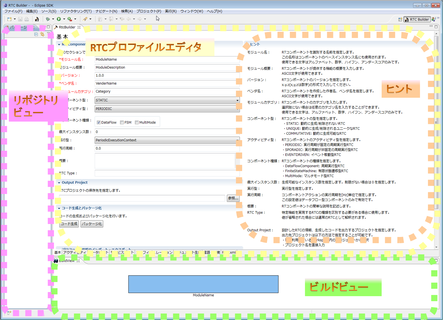
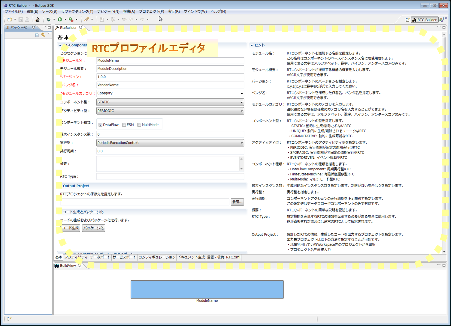
RTC Builder has the following screen composition.
| № | screen element name | description |
| 1 | RTC Profile Editor | Edit the profile, data port definitions, service port definitions, configuration definitions, and other extended profiles that are the RT component specifications. |
| 2 | Build view | It graphically displays the RT component and data port, service port, service interface being edited with icons. |
| 3 | Repository view | Display information on the selected RT repository. |
Screen structure and functions (RTprofile editor version)
- (G)Basic profile input page
- (G)Activity Profile Input Page
- (G)Data port/profile input page
- (G)Service port/profile input page
- (G)Configuration profile input page
- (G)Document Information Setting Page
- (G)Language/environment information input page
- (G)RTC profile XML edit page
- (G)Description method of constraint information
This section describes the RT profile editor.
The RT profile editor consists of the following pages.
| № | screen element name | description |
| 1 | Basic profile input page | Enter the basic information of the component, such as RT component profile information. |
| 2 | Activity profile | Specify activity information etc. supported by the RT component. |
| 3 | Data port profile | Enter the data port profile that comes with the RT component. |
| 4 | Service port profile | Enter the service port that comes with the RT component and the service interface profile attached to the service port. |
| 5 | configuration | Enter user-defined configuration parameter information and system configuration information to be set for the RT component. |
| 6 | Document generation | Enter various document information to be added to the RT component to be generated. |
| 7 | Language/environment | Enter information on execution environment such as code selection and OS to generate. |
| 8 | RTC.xml | It displays/edits RtcProfile generated based on the set information in XML format. |
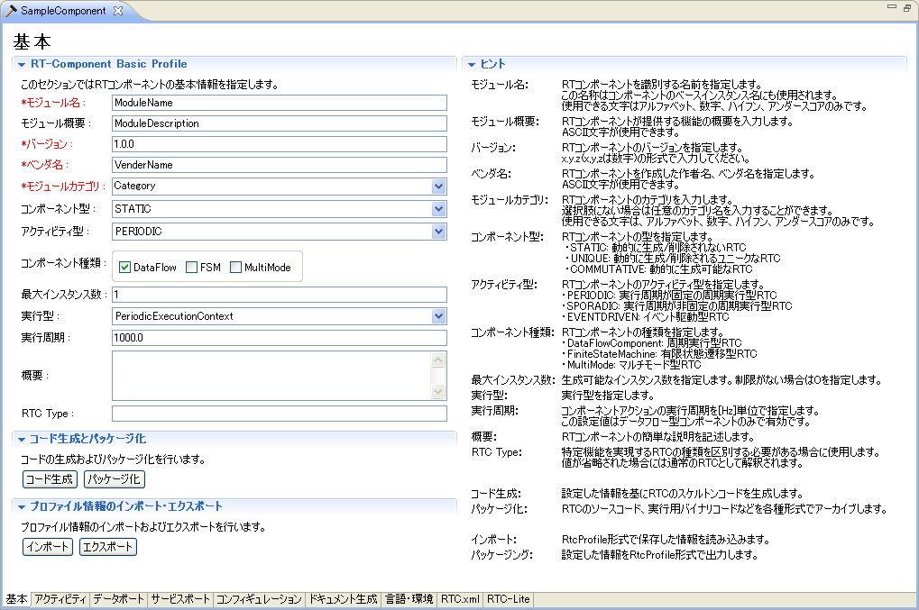
(G)Basic profile input page
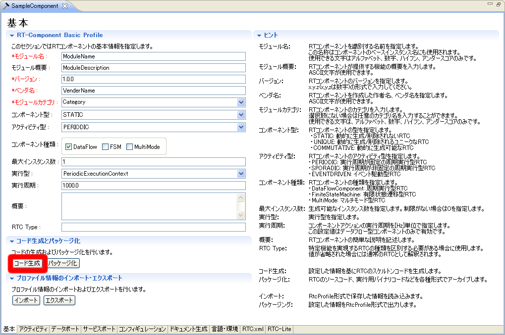
This page is for entering basic information on components such as RT component profile information.
Each input item will be explained below.
| Item | Description | Required |
| RT-Component Basic Profile | ||
| Module name | The name that identifies the RT component. Required input items. This name is used as the name of the component in the generated source code. Only alphameric characters can be entered. | ○ |
| Module overview | A brief summary description of the RT component. | - |
| Version | Version of the RT component. Enter the version number in a format like principle x.y.z. | - |
| Vendor name | The vendor name that developed the RT component. | ○ |
| Module category | It is a category of RT components. | ○ |
| Component type | Type of RT component. You can specify from the following options. ・STATIC:It is a statically existing RTC type. Dynamic creation and deletion are not performed. ・UNIQUE:Although it can generate/delete dynamically, each component holds a unique state inside, and it is a type of RTC which is not necessarily exchangeable. ・COMMUTATIVE:It is an RTC of the type in which generated components can be exchanged because it can be generated and deleted dynamically and has no internal state. |
○ |
| Activity type | The activity type of the RT component. You can specify from the following options. ・PERIODIC :Activity type that executes RTC action at regular intervals ・SPORADIC :Activity types that perform RTC actions irregularly ・EVENT_DRIVEN :Activity type where RTC action is event driven |
○ |
| Component type | The type of execution form of the RT component. You can choose from the following options. (Multiple choices can be combined) ・DataFlow : Execution form for periodically executing actions ・FSM : A form in which an action is executed by an external event ・MultiMode : Execution form with multiple operation modes |
○ |
| Maximum number of instances | Maximum number of RT component instances. Please enter a natural number. | - |
| Execution type | Type of ExecutionContext. You can choose from the following. ・PeriodicExecutionContext : ExecutionContext for performing periodic execution ・ExtTrigExecutionContext : ExecutionContex which executes by external trigger |
○ |
| Execution cycle | ExecutionContext execution cycle. A positive double type number can be input (unit Hz). | - |
| Overview | A description of the RT component. | - |
| RTC Type | Specify this when it is necessary to distinguish RT components that realize specific functions. | - |
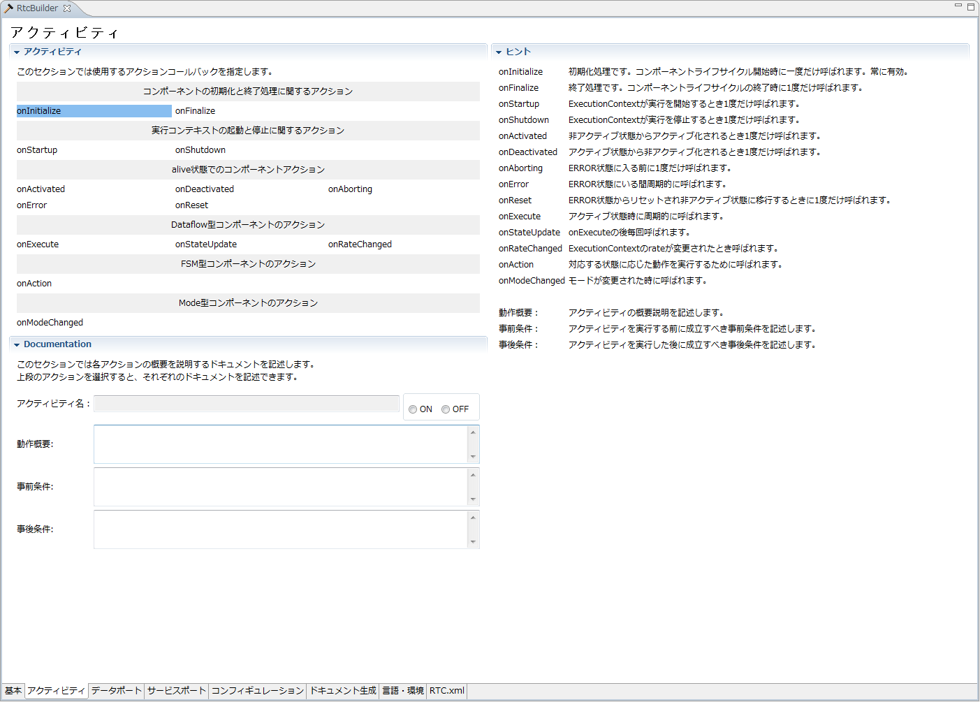
(G)Activity Profile Input Page
This page is where you enter information on the activities supported by the RT component you are generating.
The content of the Documentation section is set for each activity. In the Documentation section, contents corresponding to the selected activity are displayed.
Each input item will be explained below.
| Item | Description | Required |
| Activity Profile | ||
| onInitialize | It is initialization processing. It is only called once at the beginning of the component lifecycle. | - |
| onFinalize | It is termination processing. It is only called once at the end of the component lifecycle. | - |
| onStartup | It is only called once when the ExecutionContext starts execution. | - |
| onShutdown | Called only once when ExecutionContext stops execution. | - |
| onActivated | It is only called once when activated from an inactive state. | - |
| onDeactivated | It is only called once when deactivated from the active state. | - |
| onAborting | It is only called once before entering the ERROR state. | - |
| onError | Called while in the ERROR state. | - |
| onReset | It is only called once when transitioning from the ERROR state to the inactive state. | - |
| onExecute | It is called periodically during active state. | - |
| onStateUpdate | It is called each time after on_execute. | - |
| onRateChanged | Called when ExecutionContext's rate is changed. | - |
| onAction | It is called to perform actions according to the corresponding state. | - |
| onModeChanged | It is called when the mode is changed. | - |
| Documentation | ||
| Activity Name | Displays the name of the currently selected activity. | - |
| Outline of operation | Describe a summary description of the actions performed by the target activity. | - |
| Pre-conditions | Describe the preconditions to be met before executing the target activity. | - |
| Postcondition | Describe postconditions that will be established after executing the target activity. However, if the target activity is executed with the precondition not being satisfied, the establishment of the postcondition is not guaranteed. | - |
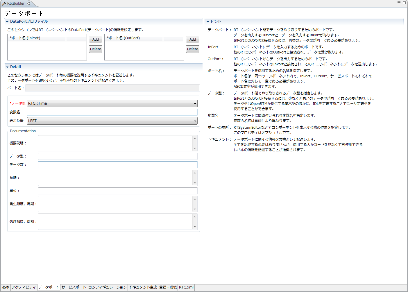
(G)Data port/profile input page
This page is for entering information on the data port attached to the RT component.
To add a new port (InPort/OutPort), click the [Add] button for each section. In addition, you can delete the selected port by clicking the [Delete] button of each section. The contents of the document section can be set for each port. In the document section, the contents corresponding to the selected port are displayed. Each input item will be explained below.
| Item | Description | Required |
| DataPort profile | ||
| Port name | It is the name of DataPort. Only half-width alphanumeric characters can be entered. Port names can not overlap with Data OutPort and Service Port. | ○ |
| Detail | ||
| Port name | Displays the currently selected Data Port in the format of "Port name (InPort/OutPort)". | - |
| Data type | The data type handled by DataPort. The data type defined in IDL specified on the setting screen is available. |
○ |
| Variable name | Variable name corresponding to DataPort. | - |
| Display position | The display position of Data InPort in the build view. | ○ |
| Outline explanation | Describe the overview of the data port. | - |
| Data type | Describe the type handled by the data port. | - |
| The number of data | Describe the number of data, such as when the data becomes an array. | - |
| meaning | Describe the meaning of the data. | - |
| unit | Describe the data unit. | - |
| Occurrence frequency | Describe the data generation frequency and cycle. | - |
| Processing speed | Describe the data processing speed and processing cycle. | - |
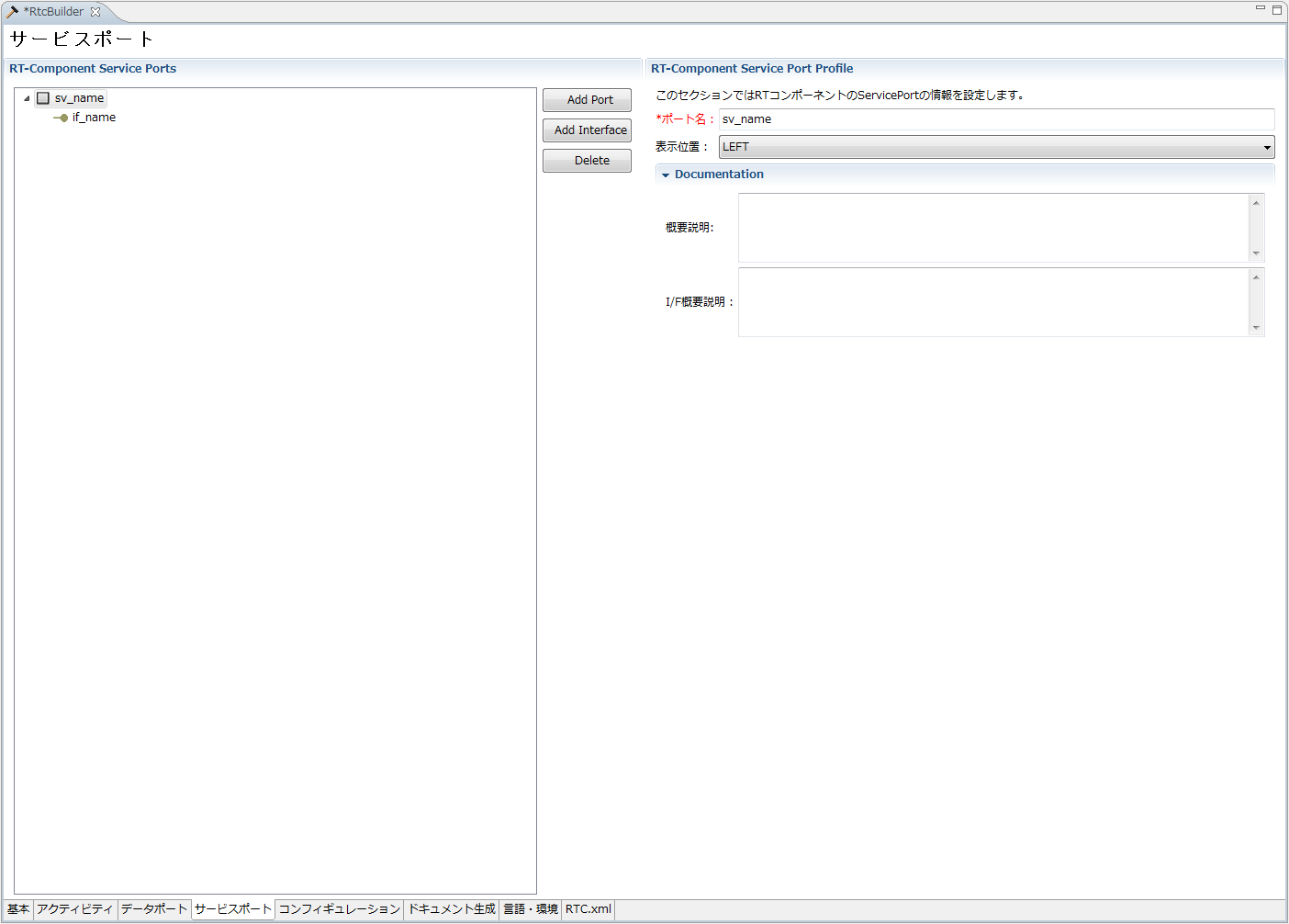
(G)Service port/profile input page
This page is for entering information on the service port attached to the RT component.
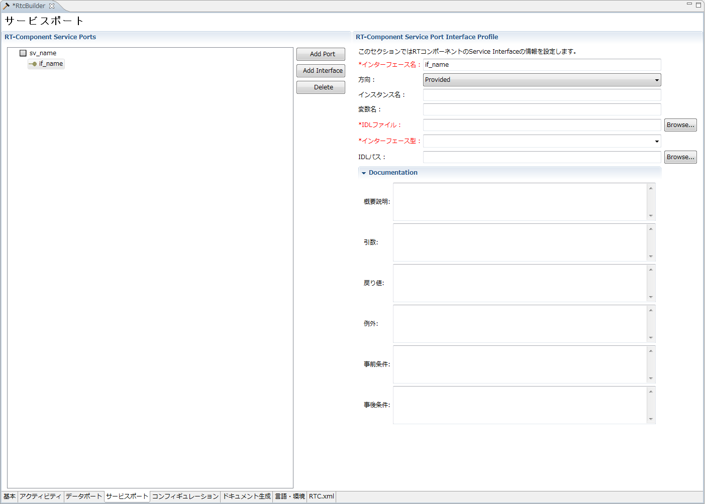
You can add a new service port by selecting "Add Port" in the "RT-Component Service Ports" column on the left side of the screen. With the service port selected in "RT-Component Service Ports" on the left side of the screen, you can add a new service interface by selecting "Add Interface". You can delete the selected port/interface by selecting [Delete] with the service port or service interface selected on "RT - Component Service Ports" on the left side of the screen. Each input item will be explained below.
| Item | Description | Required |
| RT-Component Service Port Profile | ||
| Port name | Name of service port. Only half-width alphanumeric characters can be entered. Data InPort, Data Out Port, Service Port name can not be duplicated. |
○ |
| Display position | This is the display position of the service port in the build view. | ○ |
| Documentation | ||
| Outline Description | Describe an overview description of the service port. | - |
| I/F Outline Description | Describe the outline of the service interface attached to the service port. | - |
| Item | Description | Required |
| RT-Component Service Port Interface Profile | ||
| Interface name | Name of the service interface. Only half-width alphanumeric characters can be entered. Service interface names can not overlap. |
○ |
| direction | Type of service interface. You can choose from the following options. ・Provided:Provided interface (for Service Provider) ・Required:Request interface (for Service Consumer) |
○ |
| Instance name | The instance name of the service interface. Only half-width alphanumeric characters can be entered. | ○ |
| Variable name | The variable name of the service interface. If omitted, use the instance name. | - |
| IDL file | Specify the IDL file name to be used in the service interface. Click the [Browse ...] button to display the file selection dialog. | ○ |
| Interface type | The type of service to be used in the service interface. When IDL file is specified, type information defined in IDL is displayed. Only half-width alphanumeric characters can be entered. | ○ |
| IDL Path | It is IDL's search path. When you click the [Browse ...] button, the directory selection dialog is displayed. | - |
| Documentation | ||
| Outline explanation | Describe an overview of the service interface. | - |
| argument | Describe the arguments of the service interface. | - |
| Return value | Describe the return value of the service interface. | - |
| exception | Describe the exception of the service interface. | - |
| Pre-conditions | Describe the preconditions that should be satisfied before the operation of the service interface is executed. | - |
| Postcondition | Describe the posterior condition that satisfies the operation of the service interface after execution. | - |
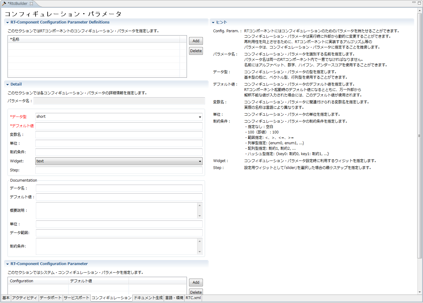
(G)Configuration profile input page
This page is for entering user-defined configuration parameter information to be set to RT component and other system configuration information.
To add new user-defined configuration parameter information and system configuration information, click the [Add] button in each section. In addition, you can delete the selected configuration information by clicking the [Delete] button of each section.
The contents of Detail section and Documentation section can be set for each user defined configuration parameter. In each section, the contents set for the selected user-defined configuration parameter are displayed.
Each input item will be explained below.
| Item | Description | Required |
| RT-Component Configuration Parameter Definitions | ||
| name | It is the name of the user defined configuration parameter. Only half-width alphanumeric characters can be entered. User defined configuration parameter names can not be duplicated. |
○ |
| Detail | ||
| Parameter name | Displays the currently selected user-defined configuration parameter. | - |
| Data type | The data type of the user-defined configuration parameter. The data type defined in IDL specified on the setting screen is available. |
○ |
| Default value | Default value for user defined configuration parameter. Any value including double-byte character can be set. | ○ |
| Variable name | The variable name of the user-defined configuration parameter. Only half-width alphanumeric characters can be entered. | - |
| unit | It is a unit of user defined configuration parameter. | - |
| Constraint condition | Describe constraints on user-defined configuration parameters. Regarding the description method of constraint conditions, Constraint information description method Please refer to. | - |
| Widget | Specify the control to be used when setting the configuration parameters in the ConfigurationView of RTSystemEditor. You can choose from the following values. ・text:Text box (default setting) ・slider:slider ・spin:Spin button ・radio:Radio button ・check:Checkbox ・ordered_list:Ordered list |
○ |
| Step | When "slider" is selected as the input control, specify the step width of the slider. | - |
| Parameter name | Displays the currently selected user-defined configuration parameter. | - |
| Data name | Describe the name of the user defined configuration parameter. | - |
| Default value | Describe the default value of the user defined configuration parameter. | - |
| Outline explanation | Write an overview description of user-defined configuration parameters. | - |
| unit | Describe the unit of the user defined configuration parameter. | - |
| Data range | Describe the data range of the user defined configuration parameter. | - |
| Constraint condition | Describe constraints on user defined configuration parameters. | - |
| RT-Component Configuration Parameter | ||
| Configuration | The name of the configuration to configure. Select from the list. | ○ |
| Default value | It is the default value of the configuration target setting. For items for which default values are set in advance, default values are set when name is selected. | - |
(G)Document Information Setting Page
Enter various document information on the RT component to be generated.
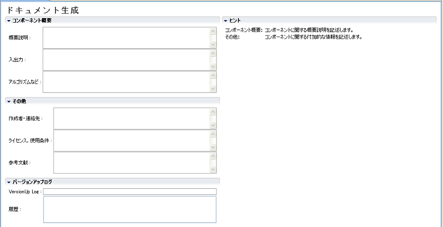
The information entered on this page is embedded in the generated code in doxygen format.
Each input item will be explained below.
| Item | Description | Required |
| Component summary | ||
| Outline explanation | Describe an overview description of the RT component to be generated. | - |
| Output | Describes a brief description of input/output of RT component. | - |
| Algorithm etc. | Describe the algorithm etc. used by RT component. | - |
| Other | ||
| Author/Contact | Write information on the creator and contact information of the RT component. | - |
| License, terms of use | Describe the license information of the RT component and information on the usage conditions. | - |
| References | Describe bibliographic information. | - |
| Version upgrade log | ||
| VersionUp Log | Write log information on the current change contents. | - |
| License, Terms of Use | Display log information at past version up. | - |
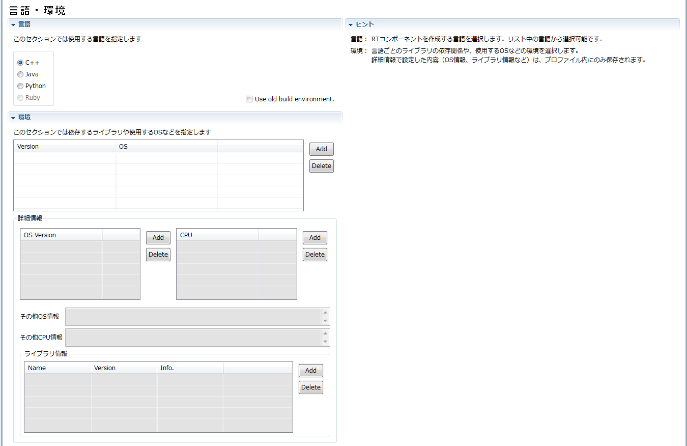
(G)Language/environment information input page
It is a page to input the language selection of the template · source code to be generated based on the RT component specification you entered, the execution environment such as OS, dependent libraries, etc.
Sections are divided for each language to be generated. Please select the section of the language you want to generate and enter the setting information specific to each language. If you select a section, all other sections are closed. The language template code for the section that was selected when code generation is executed (when clicking the [Generate Code] button on the basic profile input page) is generated. Each input item will be explained below.
| Item | Description | Required |
| language | Specify the target language. | ○ |
| Use old build environment. | When this check box is on, code similar to the old version (format not using Cmake) is generated. | - |
| environment | ||
| Version | Set the version information of the language implementing RTC to be generated. | - |
| OS | Set the OS information on which RTC to be generated operates. | - |
| OS Version | Set the version information of the OS on which RTC to be generated operates. | - |
| CPU | Set the CPU architecture information on which RTC to be generated operates. | - |
| Other OS information | For supplemental information other than version information, set up the OS on which RTC to be generated operates. | - |
| Other CPU information | For supplementary information other than the architecture information for the CPU on which RTC to be generated operates. | - |
| Library information | ||
| Name | Specify the name of the external library used by the target RTC. | ○ |
| Version | Specify the version information of the external library used by the target RTC. | - |
| Info. | Specify supplemental information of the external library used by RTC to be generated. | - |
(G)RTC profile XML edit page
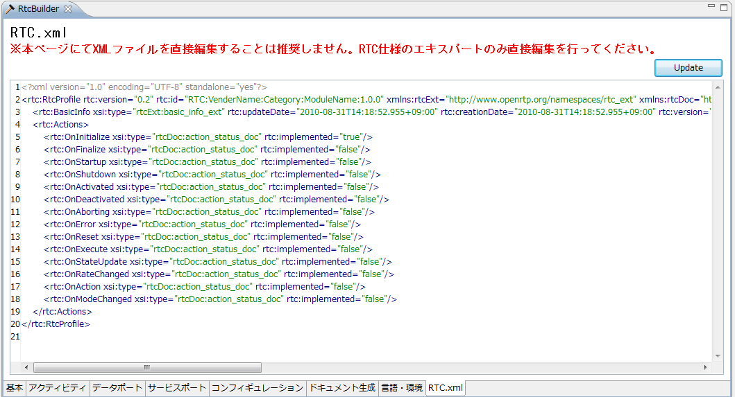
This page is for checking and editing the contents of the XML file (RTC.xml) that describes the RT component specification you entered. It is used to check the contents set on other pages and to directly edit the items that can not be input from the GUI screen.
The contents of the displayed RT component specification are created based on the contents set on other pages when switching to this page.
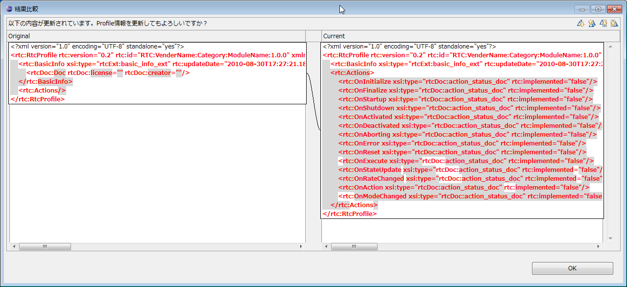
By clicking the [Update] button at the upper right of the screen, you can reflect the settings and changes made on this page to other pages (it will only be reflected on other pages, not writing to the file). In addition, the following screen will be displayed, you can check the change point. Please click [OK] to reflect the correction contents on other page.
The contents entered directly on this page are saved only when saving in the state displaying this page. After editing the contents on this page, if you save it with the other page open, the item you entered on the other page takes precedence. When saving the contents of this page, validation is performed according to the schema definition of RTC.xml. If an error is found during validation, the following error message will be displayed. Please correct the corresponding part by referring to the displayed contents.
(G)Description method of constraint information
The constraints on data ports and user defined configuration parameters are set with the following format.
| Setting contents | Setting form |
| Not specified | Blank |
| 100(immediate) | 100 |
| 100 or more | x >= 100 |
| 100 or less | x <=100 |
| Over 100 | x >100 |
| Less than 100 | x < 100 |
| 100 or more and 200 or less | 100 <= x <= 200 |
| 100 to less than 200 | 100 < x < 200 |
| Enumeration type | (9600,19200,115200) |
| Array type | x >100, x > 200, x > 300 |
| Hash type | {key0: 100 < x < 200, key1: x >= 100} |
Screen structure and functions (Build view)
The Build view is a view for graphically displaying the contents of the RT component being created. An example of the build view display is shown below.
In the build view, the name of the RT component you set, the number and name of the data port (InPort/OutPort), the number and name of the service port, the number and name of the service interface are displayed. In addition, each port is displayed at the display position set on each setting screen.
(G)Display build view
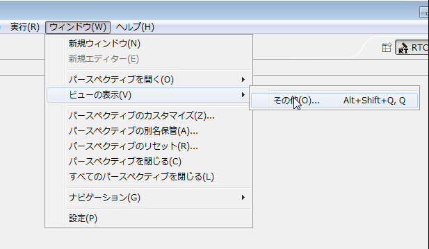
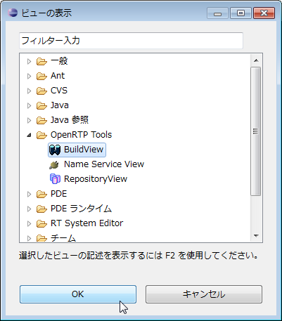
If "Build view" is not displayed when switching "RTCBuilder" perspective, it can be displayed by the following procedure. From the menu at the top of the screen, select Window> Show View> Other. On the displayed "View View" screen, select [OpenRTP Tools] > [BuildView].
Code generation/Save and load
(G)Code generation
After setting various profile information of RT target component to be generated, generate template code. When you click the [Generate Code] button on the basic profile input page, template code is generated according to the entered profile information.
The template files generated at the time of executing code generation when selecting each language are as follows.
- C++ ( When you do not select the check box of "Use old build environment." )
| file name | Description |
| <RTC name> Comp.cpp | Code to launch the RT component. |
| <RTC name>.h | It is the header of the RT component body. |
| <RTC name>.cpp | This is the code of the RT component body. |
| <Service type name>SVC_impl.h | It is the header of the service provider.(*) Only Type specified by ServiceProvider is output. |
| <Service type name>SVC_impl. cpp | The implementation code of the service provider.(*) Only Type specified by ServiceProvider is output. |
| CMakeLists.txt | It is a configuration file file for CMake. |
| doc/ | |
| doxyfile.in | It is a setting file file for Doxygen. |
| cmake/ | |
| uninstall_target.cmake.in | Uninstall target addition template file (for CMake) |
| cpack_options.cmake | WiX package creation module (for CMake/WiX) |
| License.rtf | License display included in package information (for CMake/WiX) |
| wix.xsl.in | Template for specifying files to be included in WiX package (for CMake/WiX) |
| cmake/Modules/ | |
| FindOpenRTM.cmake | OpenRTM-aist Environment setting acquisition module (for CMake) |
- C++ ( When the check box of [Use old build environment.] Is turned on )
| file name | Description |
| <RTC name> Comp.cpp | Code to launch the RT component. |
| <RTC name>.h | It is the header of the RT component body. |
| <RTC name>.cpp | This is the code of the RT component body. |
| <Service type name>SVC_impl.h | It is the header of the service provider.(*) Only Type specified by ServiceProvider is output. |
| <Service type name>SVC_impl. cpp | The implementation code of the service provider.(*) Only Type specified by ServiceProvider is output. |
| Makefile.<RTC name> | Makefile for compiling. |
| <RTC name>_vc8.sln | It is a solution file for Visual Studio 2005. |
| <RTC name>_vc8.vcproj | RT component project file for Visual Studio 2005. |
| <RTC name>Comp_vc8.vcproj | Project code for start code for Visual Studio 2005. |
| <RTC name>_vc9.sln | It is a solution file for Visual Studio 2008. |
| <RTC name>_vc9.vcproj | RT component project file for Visual Studio 2008. |
| <RTC name>Comp_vc9.vcproj | Project code for start code for Visual Studio 2008. |
| Copyprops.bat | Property file This is a batch file for copying. |
| User_config.vsprops | User defined property file. |
| OpenRTM-aist.vsprops | Property file for OpenRTM-aist. |
- Java
| file name | Description |
| <RTC name>Comp.java | Class for starting RT component. |
| <RTC name>.java | Component Profile of RT component, Initialization processing, etc. |
| <RTC name>Impl.java | It is the body of the RT component. |
| build_<RTC name>.xml | It is a file for RT component build. |
| <Service type name> SVC_impl.java | Implementation class of the service provider.(*) |
| CMakeLists.txt | It is a configuration file file for CMake. |
| doc/ | |
| doxyfile.in | It is a setting file file for Doxygen. |
| cmake_modules/ | |
| cmake_javacompile.cmake.in | Model file for adding Java compilation targets (for CMake) |
| FindOpenRTMJava.cmake | OpenRTM-aist-Java environment setting acquisition module (for CMake) |
| cmake/ | |
| uninstall_target.cmake.in | Uninstall target addition template file (for CMake) |
| cpack_options.cmake | WiX package creation module (for CMake/WiX) |
| License.rtf | License display included in package information (for CMake/WiX) |
| cpack_resources/ | |
| wix.xsl.in | Template for specifying files to be included in WiX package (for CMake/WiX) |
- Python
| file name | Description |
| <RTC name>.py | This is the code of the RT component. |
| <Service type name>_idl.py | |
| <Service type name>_idl_example.py | Implementation file of the service provider.(*) |
| CMakeLists.txt | It is a configuration file file for CMake. |
| doc/ | |
| doxyfile.in | It is a setting file file for Doxygen. |
| cmake_modules/ | |
| FindOpenRTMPython.cmake | OpenRTM-aist-Python Environment setting acquisition module (for CMake) |
| cmake/ | |
| uninstall_target.cmake.in | Uninstall target addition template file (for CMake) |
| cpack_options.cmake | WiX package creation module (for CMake/WiX) |
| License.rtf | License display included in package information (for CMake/WiX) |
| cpack_resources/ | |
| Description.txt | Description included in package information (for CMake) |
| License.txt | License display included in package information (for CMake/Linux) |
| wix.xsl.in | Template for specifying files to be included in WiX package (for CMake/WiX) |
- Only #include directives can be used in the preprocessor. (#ifdef etc. are simply ignored)
- The operation to be created is only the operation of the directly specified interface, and the operation inherited from the parent is not included.
(G)Output selection
RtcBuilder displays a confirmation screen for selecting which output to use, if a file with the same name as the generated file already exists in the output destination and there is a difference in the output content between the existing file and the generated file I will.
For output selection, select from the following three output candidates.
- Original: Leave existing files as they are
- Merge: Merge using merge block ( *1 )
- Generate: Overwrite with newly generated content
*1 Merge overwrites only the range enclosed by the <rtc-template block="block"> tag with the latest generation content. In this generated template, this tag encloses the range that the user does not change beforehand. Please keep in mind that this tag will disappear after merging, so please do not modify it.
(G)Perspective switching
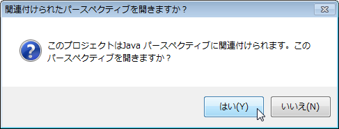
If the development environment plug-in of the target language is installed, a confirmation message of perspective switching will be displayed after code generation is executed. If the target plug-in is installed, the following message will be displayed, so please select whether to switch the perspective.
The relationship between the generated language and the development environment plug-in is as follows.
- Java: JDT (Java Development Tools) → It is a development environment included in Eclipse in advance.
- C++: CDT (C/C++ Development Tooling)
- Python: PyDev
If the development environment plug-in for each language is installed and the output target project is a newly created project, the target language attribute is set in the property of each project.
(G)Generation file packaging function
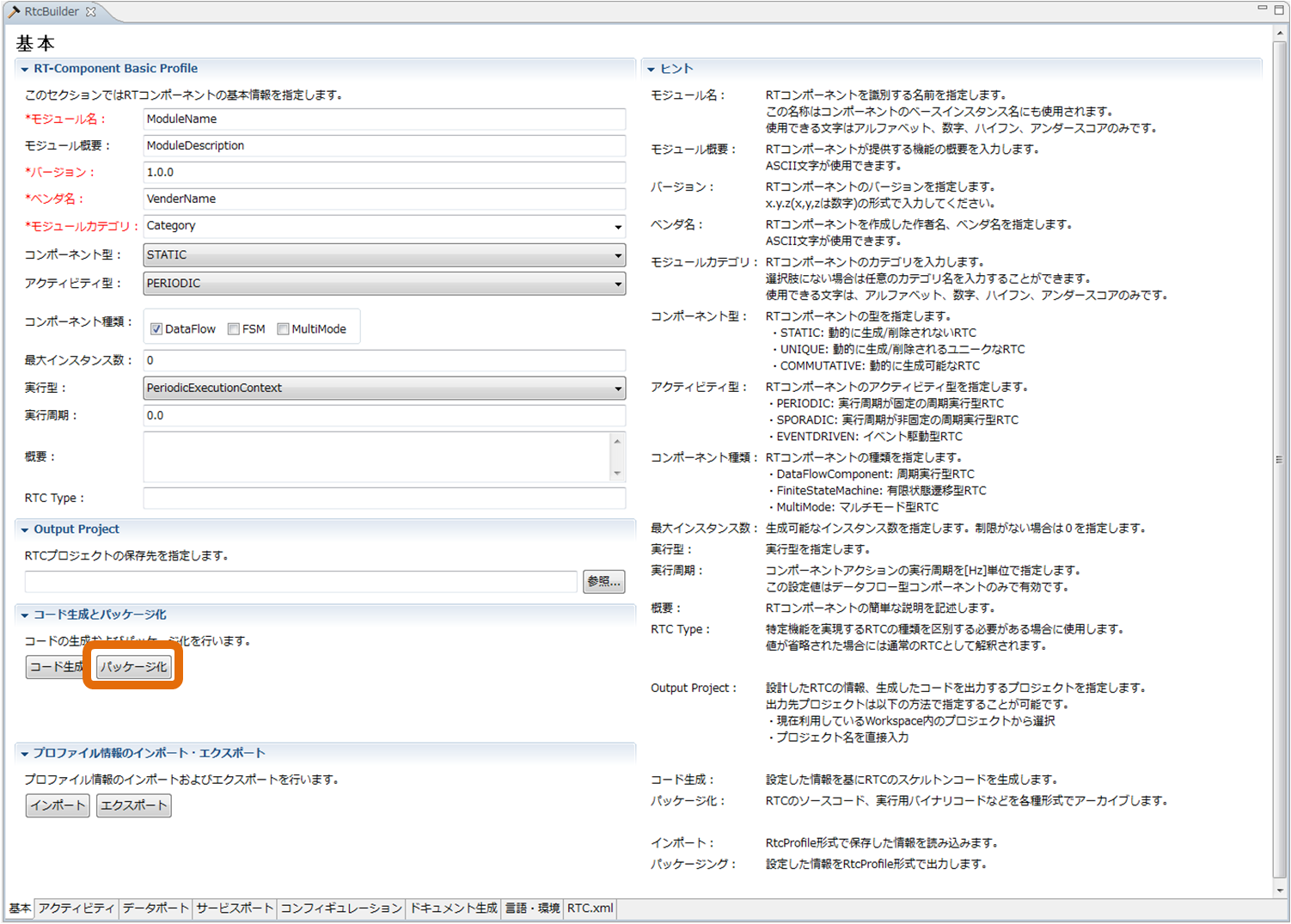
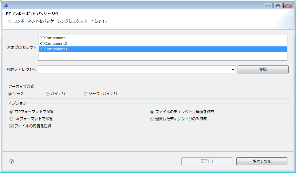
It is a function to archive the generated template file, binary file for execution of the RT component created based on the template file, etc. in various formats. Clicking on the [Package] button on the basic profile entry page will display the "RT Component Packaging" screen for setting the packaging content.
Each item is explained below.
| Item | Description |
| Target project | Please select the project to be packaged. |
| Destination directory | Please enter the directory to output packaged artifacts. By using the "Browse" button, the directory selection dialog will be displayed. |
| Archive method | Please select the format of the archive to be created. |
| Optional | A brief description of the operation within each action. Optional items. |
| Archive format | It is possible to create an archive using the ZIP format and an archive using the tar format. Please select the format format to use. |
| Compression of archive contents | To compress the contents of the archive, please select the check box. |
| Directory structure | Please select whether to archive with the directory structure of the project to be archived as it is, or archive all in the root directory. |
For each archive method ("source" "binary" "source+binary"), which file type to include in the archive can be set in the "setting screen" described later.
(G)Saving and Loading Settings
RTCBuilder allows you to save the contents entered in the RTC Profile Editor in the RTC profile XML (RTC.xml) and reload the saved content.
(G)Save
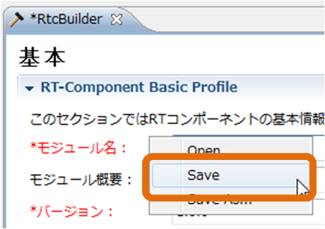
The contents entered in RTC profile editor can be saved in RTC profile XML (RTC.xml). The input contents can be saved by the following operation.- Right-click on the editor and select [Save] or [Save As ...] from the displayed context menu
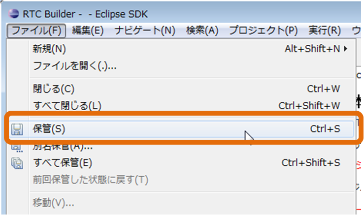
- Select [File] > [Save...] or [File] > [Save As...] on the menu bar
If you select [Save As ...], it can be saved in any project. *[Save As…] を選んだ場合、任意のプロジェクト内に保存することが可能です。
(G)Load
The RTC profile XML (RTC.xml) that saved the contents of the RTC profile editor can be read by the following operation.- Right-click the editor and select [Open] from the context menu
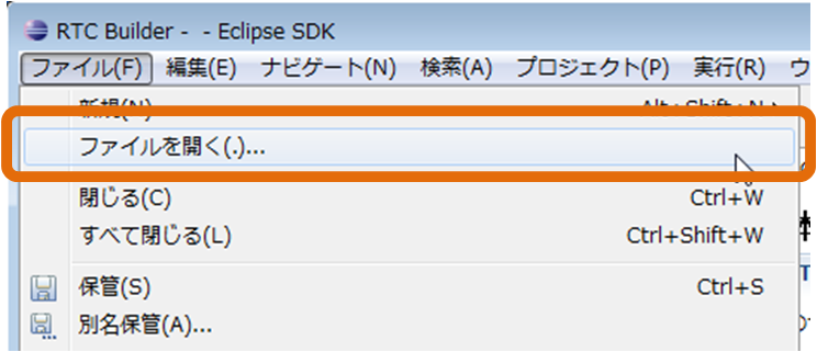
- Select [File] > [Open file...] from the menu bar
Profile export/import
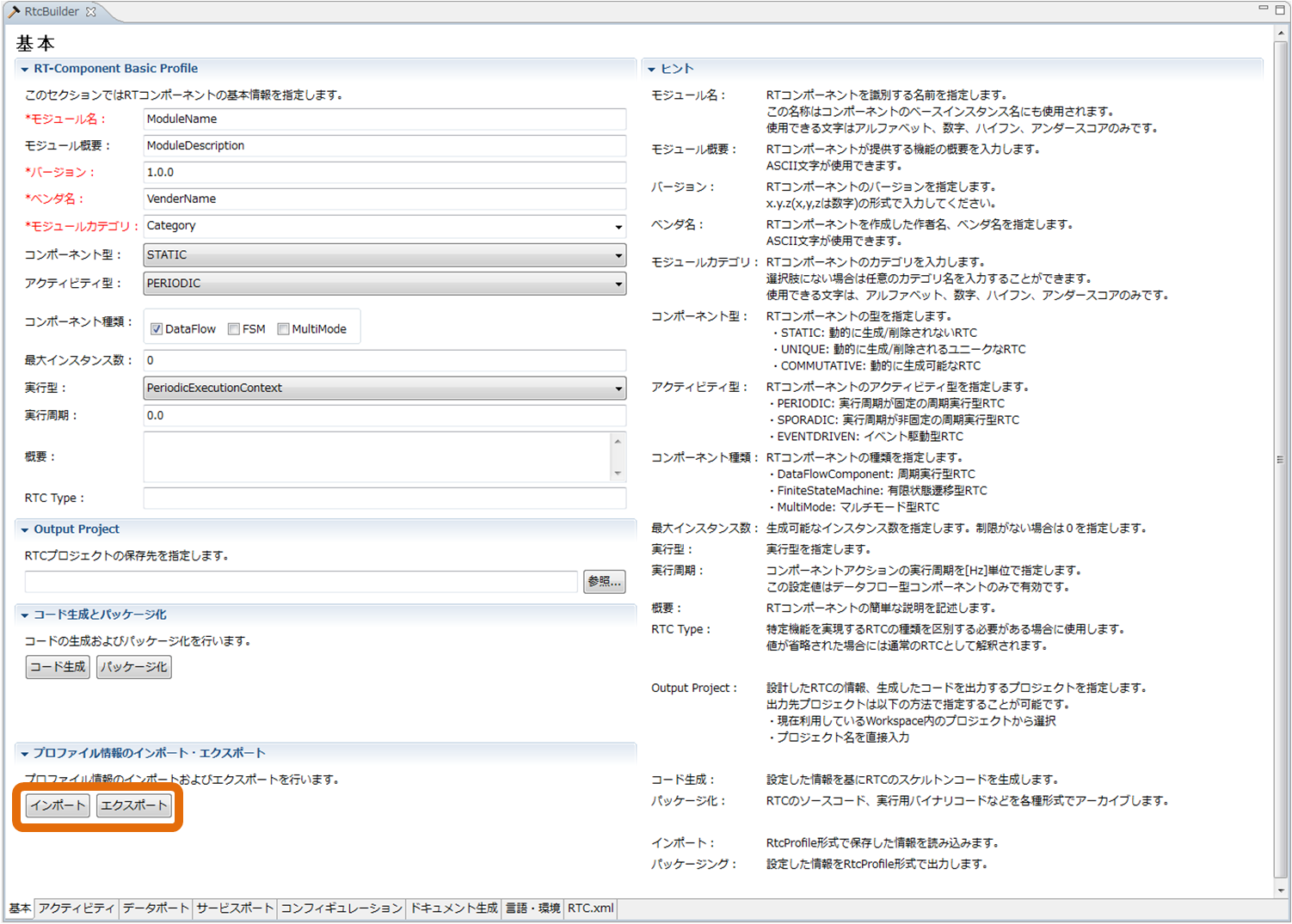
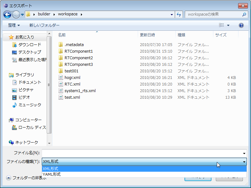
It is a function to export the contents input and set in RTC profile editor to external file in XML format, YAML format, and import the exported file. Clicking the [Export] button on the basic profile input page selects the destination for exporting profile information, and clicking the [Import] button displays the file dialog for selecting the profile information of the import source.
* The format for export processing can be selected by "File type" in "Export" dialog.
Various settings
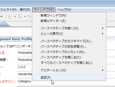
This section explains the various settings of RTC Builder. The RTCBuilder setting screen is displayed by selecting "RTCBuilder" from the "Settings" screen displayed by selecting Window > Settings .... in the upper screen menu.
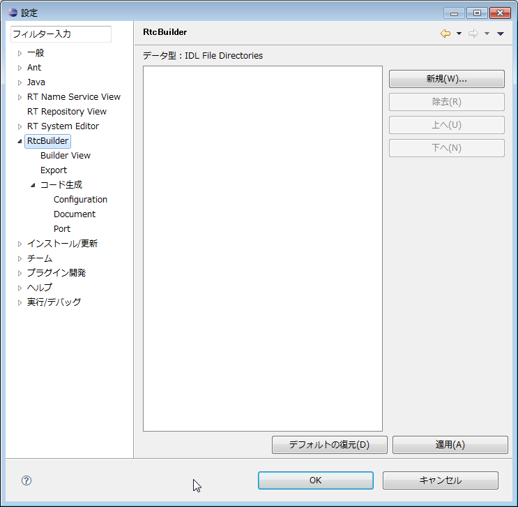
(G)Data type
You can set the location of the IDL file that defines the data type to be set with the Data Port and the Configuration parameter. To add a new IDL storage directory, click the [New] button. In addition, you can delete the selected IDL storage directory by clicking the [Remove] button. The actual location of the IDL storage directory should be selected on the directory selection screen displayed by clicking in the "IDL File Directories" column.
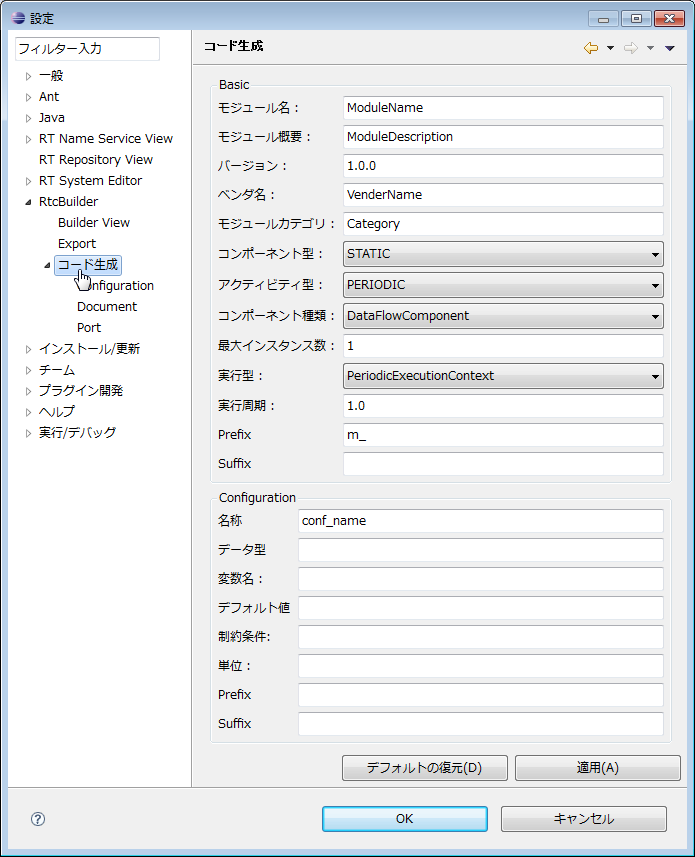
(G)Code generation
In the RTC profile editor's basic profile input page and configuration profile input page, you can set the contents set by default when new editor is displayed and when adding new item.
The default setting (contents set when clicking the [Restore Defaults] button) in this setting screen is as follows.
| Item | default value |
| Basic | |
| Component name | ModuleName |
| Description | ModuleDescription |
| Version | 1.0.0 |
| Vendor | VendorName |
| Category | Category |
| Component Type | STATIC |
| Component’s activity type | PERIODIC |
| Max. Instances | 1 |
| Component kind | DataFlowComponent |
| Execution type | PeriodicExecutionContext |
| Execution rate | 1.0 |
| Configuration | |
| Name | conf_name |
| Type | conf_type |
| Variable Name | conf_varname |
| Default Value | conf_default |
| Constraint | conf_constraint |
| Unit | |
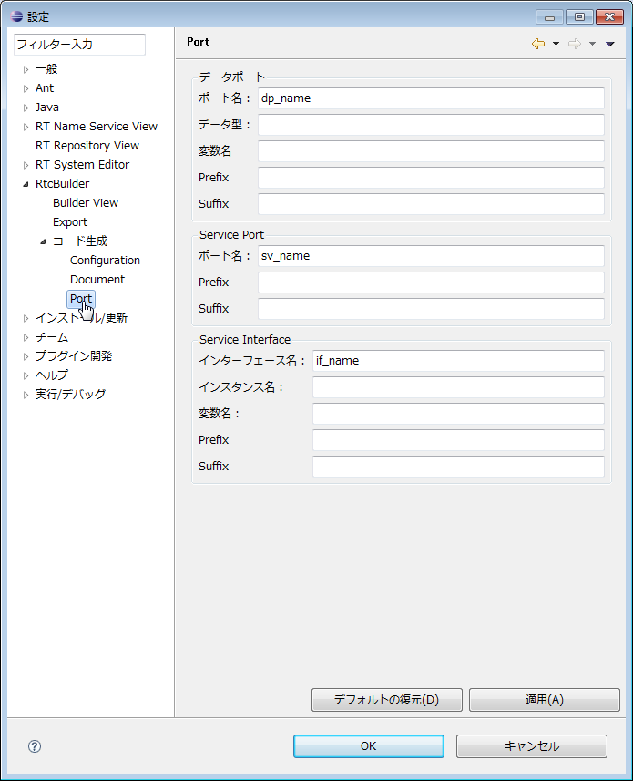
(G)Port
You can set the default settings when new items are added on the data port · profile input page and service port · profile input page of RTC profile editor.
The default setting (contents set when clicking the [Restore Defaults] button) in this setting screen is as follows.
| Item | default value |
| Data Port | |
| DataPort Name | dp_name |
| DataPort Type | dp_type |
| DataPort Variable Name | dp_vname |
| DataPort Constraint | dp_constraint |
| DataPort Unit | |
| Service Port | |
| ServicePort Name | sv_name |
| Service Interface | |
| Interface Name | if_name |
| Instance Name | if_instance |
| Variable Name | if_varname |
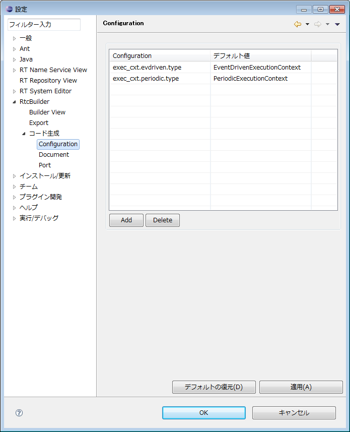
(G)Configuration
You can set items displayed in the system configuration information on the configuration profile input page of the RTC profile editor.
The default setting (contents set when clicking the [Restore Defaults] button) in this setting screen is as follows.
| Item | default value |
| exec_cxt.periodic.type | PeriodicExecutionContext |
| exec_cxt.periodic.rate | 1000 |
| exec_cxt.evdriven.type | EventDrivenExecutionContext |
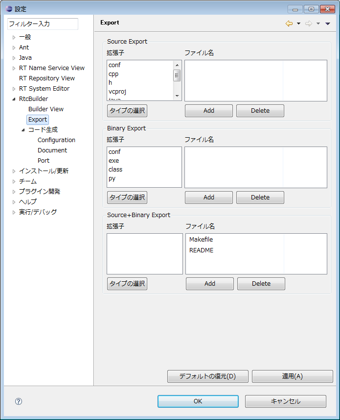
(G)Export
You can set the files to be included in each archive format of the RT component's packaging function.
The setting screen is divided into sections (Source Export, Binary Export, Source + Binary Export) for each archive format. Each section consists of an extension specification part and a file name specification part.
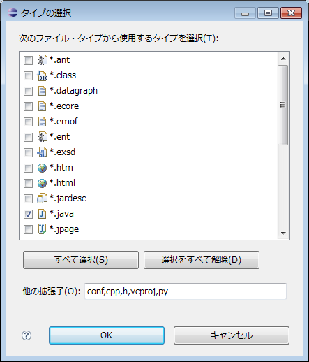
In the extension specification part, you can set the extension of the file to be included in each archive format. When you click the [Select type] button, the following type selection screen is displayed. Please select the file type you want to include in the archive.
| *Only the registered extensions are displayed in the file extension list. If you want to select a file that does not exist in the list, please enter the appropriate extension in "other extensions" column at the bottom of the screen with "," separator. |
In the file setting section, you can set the file names to include in the archive. If you click the [Add] button at the bottom of the "File name" list, a new line will be added. Please enter the file name you want to include in the archive directly. You can also delete the selected line by clicking the [Delete] button. '' In the example of the Export setting screen (section) 'in the above figure, when selecting "Source + Binary" as the archive method, the file whose extension is "cpp" "h" and the file whose file name is "Makefile "It is set to include the file which is" README "in the archive. The default setting (contents set when clicking the [Restore Defaults] button) in this setting screen is as follows.
| Item | default value |
| Source Export | |
| extension | conf, cpp, h, vcproj, java, xml, py |
| file name | Makefile, README |
| Binary Export | |
| extension | conf, exe, class, py |
| file name | README |
| Source+Binary Export | |
| extension | conf, cpp, h, vcproj, java, xml, py, exe, class |
| file name | Makefile, README |
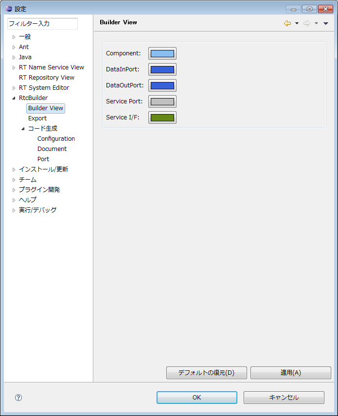
(G)Build View
You can set color information of the icon displayed in the Build View.
With each color setting button, it is possible to change the color setting of the component body, DataInPort, DataOutPort, ServicePort, ServiceInterface.
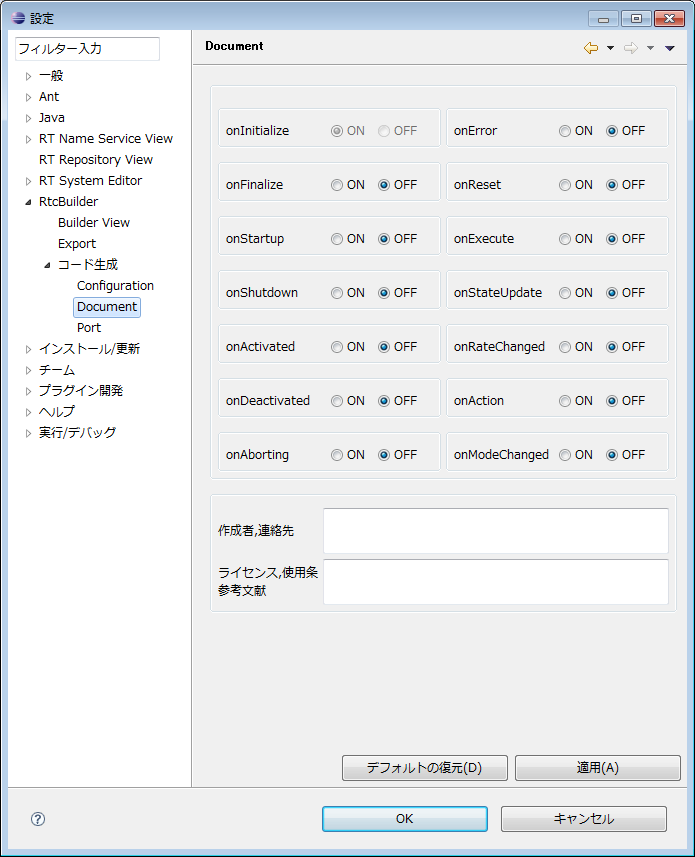
(G)Document
You can set the valid/invalid attribute (ON/OFF) of each activity.
Update method
This section describes the procedure for updating OpenRTP (RTC Builder, RTS SystemEditor generic name). Since OpenRTP is provided as an Eclipse plug-in, it operates on Eclipse.
(G)Update OpenRTP
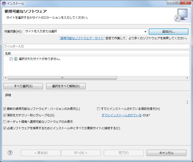
In the Eclipse menu, select Help> Install New Software.
Click the "Add" button in the "Install" dialog and add the repository. Specify the name and location as follows.- Name : OpenRTP
- Location : http://openrtm.org/pub/openrtp/stable/updates/
Check OpenRTP 1.1.0 and click the [Next] or [Complete] button.
As the inquiry about the trust of the certificate opens during the installation, please put a check mark and click the [OK] button.
After installation, if you restart according to the instructions, the update will be reflected.
(G)How to reflect on existing components
As for the project of the component which has already been generated, please deal with the following procedure etc.
- Re-read in eclipse and regenerate the code (delete the project once on eclipse and import it again)
- In eclipse's package · explorer screen, double-click RTC.xml in the project and click the [Generate Code] button
- Since the diff screen is displayed at this time, update only idl/CMakeLists.txt
For Linux and Mac, simply replace with sed.
$ sed -ie 's/\"\${ALL_IDL_SRCS}\"/ALL_IDL_SRCS/' idl/CMakeLists.txtCompiling method (Windows, CMake using, C++ edition)
I will explain how to build on Windows.
(G)Environment preparation
(G)Environment
| Visual C++ (version 2005 or later) | Vc++ development environment |
| CMake (version 2.8.5 or higher) | Tools for generating build files that are in development environment |
| Doxygen | Documentation Generator |
| Wix Windows Installer XML toolset (version 3.0 or 3.5) | Tool set for creating Windows Installer (MSI) package |
(G)Combination of versions
There is a combination of versions of Visual C++ and Wix.
| VC++ | Wix |
| 2010 | 3.5 |
| 2008 | 3.0 |
| 2005 | 3.0 |
(G)Build procedure
It shows the build procedure. The figure is VC++ 2005, CMake 2.8.5.
(G)Cmake settings
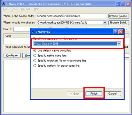
Launch the GUI version of Cmake and specify the directory.
| Where is the source code | Specifies the folder of the code generated by RTCBuilder. |
| Where to build the binaries | Specify a folder to output files such as solution/project/workspace. |
(G)Running Configure
Click the [Configure] button to execute it. Then select the platform to use. In the example, "Visual Studio 9 2008" is selected.
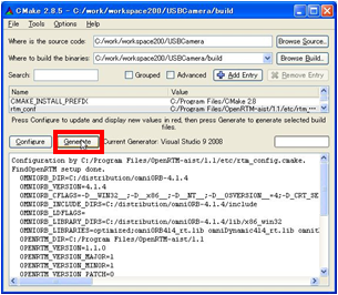
(G)Running Generate
When Configure completes normally, click the Generate button.
(G)Running VC++
Open the solution file (*.sln) in the folder specified in "Where to build the binaries".
(G)Running the build
Build solution by executing [Build] > [Build Solution].
(G)Document generation procedure
(G)Running doxygen
In the Solution Explorer, select "doxygen" and right click. So select "Build" and execute it.
(G)Documentation
Documents are generated in doc/html under the folder specified in "Where to build the binaries".
(G)Package generation procedure
Package generation uses cpack and wix that are included in CMake, but cpack does not support Wix, and can not generate packages unless it is normal. As a response, please expand the following file and replace it with one of C:\Program Files\CMake 2.8.
(G)Running doxygen
In the Solution Explorer, select "doxygen" and right click. So select "Build" and execute it.
(G)Running the PACKAGE build
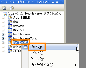
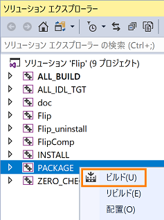
In Solution Explorer select "PACKAGE" and right click. So select "Build" and execute it.
(G)Package
The msi format installation package is generated under the folder specified in "Where to build the binaries".
rtc1.1.0- <package name> .msi
When you run this installation package, it will be installed to the following.
C:\Program Files\OpenRTM-aist\1.1\components\<Language>\<package name>
| Attachment | Size |
|---|---|
| 1.09 MB |
Compiling method (Windows, Java version)
I will explain how to build in Java.
(G)Preparation
It is necessary to install Java Development Kit 6 in advance. (Note: It will not work with Java 1.5 (5.0).)
(G)Build procedure from RTC Builder
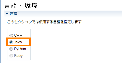
- RTC Profile Editor screen, open the [Language/Environment] tab and select [Java].
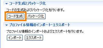
- Open the [Basic tab] and click the [Generate Code] button to generate the code.
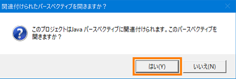
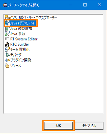
- If the development environment plug-in of the code generation target language is installed, the following confirmation message will be displayed Click [Yes]. Then select [Java (default)] in the dialog displayed and click the [OK] button.
For the Java language, JDT (Java Development Tools) is included in Eclipse in advance.
- The information of the project is displayed in the package explorer, but since it is not displayed at all, select [File] > [Update] from the menu or click the [F5] key in the package explorer to display information Updating.
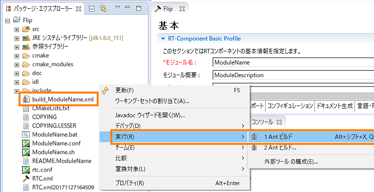
- Right-click the file of [build_ module name.xml] and select [Run] > [1 Ant Build].
- The build is executed and the build result is displayed on the console screen.
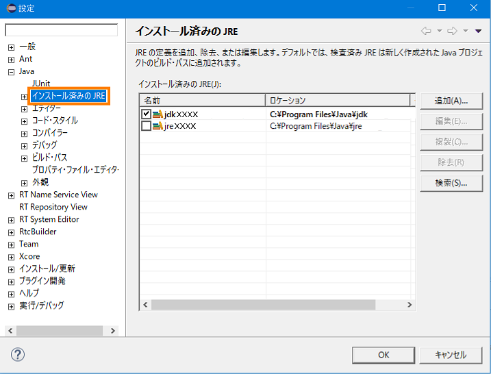
- If an error is displayed on the console screen, check if the JDK is installed correctly. Select Window > Settings > Installed JRE from the menu. Make sure that the installed JDK is selected. If it is not displayed, add the installed JDK from the [Add] or [Search] button.
Reference - New Java project can not be created as JDK 6 (1.6) compliant
- How can I Ant build with arbitrary folders set to classpath?
- An exception is displayed when building from Ant's in the Java from the command line
(G)Build procedure from the command prompt
- Download Apache Ant from the following site. Apache Ant is a software for running builds. Eclipse has built-in Ant plug-in as standard, but you need to download it in order to run build from the command prompt.
Download:the Apache Ant Website
- Unzip the Zip file and change the folder name as desired. (Eg: apache-ant-x.xx.x → ant)
- Move to any folder. (Ex:C:\Program Files\ant)
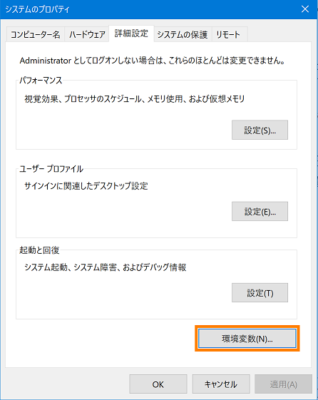
- Set environment variables. (The screen is for Windows 10)
- Open the Properties window of the system and click the [Environment Variables] button.
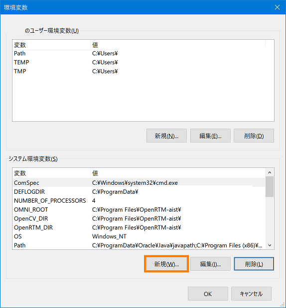
- Click "New" button in "System environment variable".
- Enter "ANT_HOME" in the variable name, "C:\Program Files\ant" in the variable value, and click the [OK] button. * The variable value specifies the path of the ant folder.
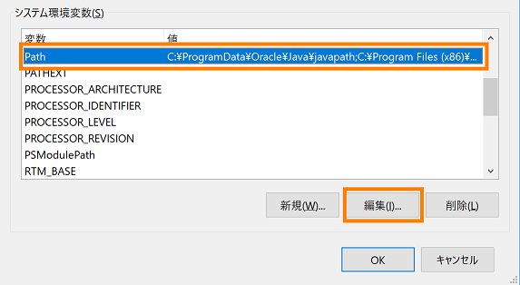
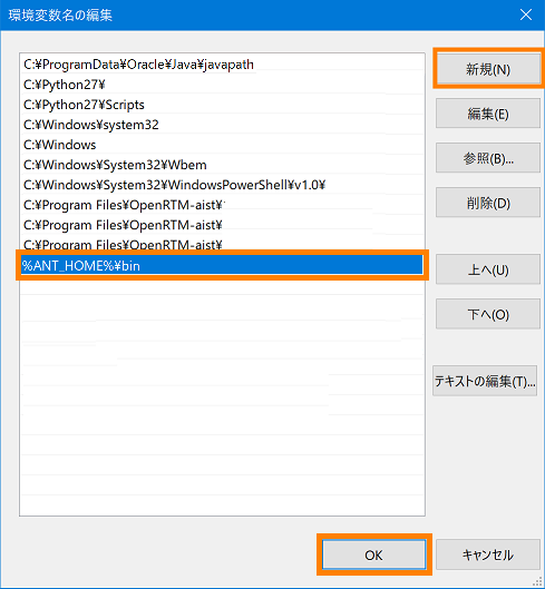
- From the "System environment variable" list, select the variable name "Path" and click the "Edit" button.
- Click the [New] button, enter "%ANT_HOME%\bin" and click the [OK] button.
- Set JAVA_HOME. It is unnecessary if already set.
Click "New" button in "System environment variable".
- Enter "JAVA_HOME" for the variable name and "C:\Program Files\Java\jdkx.x.x.x.x_xxx" for the variable value and click the [OK] button.
The variable value specifies the path of the Java installation destination folder.
- Return to the system property screen and click the [OK] button to close the screen.
- Open the Properties window of the system and click the [Environment Variables] button.
- Reboot the PC.
- Reboot, start the command prompt and enter "ant -version" to check the version of Apache Ant.
Similarly, type "java-version" and check the Java version.
- Build from the command prompt.
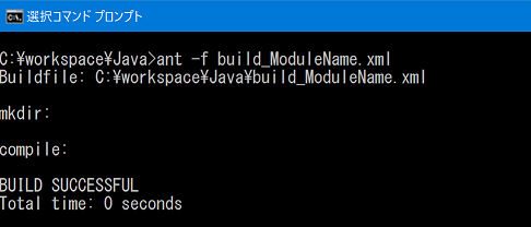
When you enter the following command in the folder of the specified RTC project, the build will start.If build succeeds, the following display will be displayed.ant -f build_*****.xml (***** is the module name)
Package creation using CPack (common settings on Windows/Linux)
(G)Introduction
CMake has a function to create an installer package by CPack. RT components generated using OpenRTP version 1.2.0 or later can create installer packages without changing the CMake settings generated by RTC Builder. For Windows environment, you can create msi installer, Linux Ubuntu or Debian deb package, and Fedora environment rpm package.
(Note) However, this package can be created with OpenRTP 1.2.0 version only in C++ or Python RTC, not in Java RTC.
Installation of OpenRTP 1.2.0 version is introduced on the download page of OpenRTM-aist 1.2.0 version.
(G)Advance preparation
Install the software necessary for installer and package creation.
(G)Windows environment
In addition to the software displayed when installing OpenRTM - aist, the following software must be installed.
| WiX Toolset | msi It is necessary to create an installer. |
| Graphviz | Documents can include flowcharts, system diagrams, etc. |
(G)Installing WiX Toolset
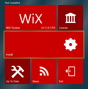
- Launch the installer and click the [install] button to start the installation.
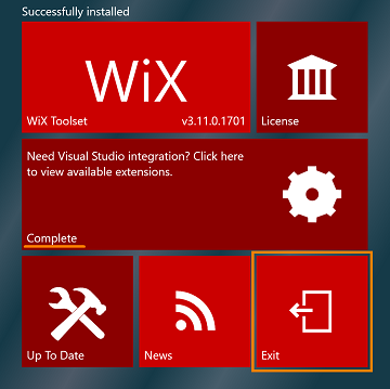
- Installation is complete when "Complete" is displayed on the [install] button. Click the [Exit] button.
(G)Installing Graphviz
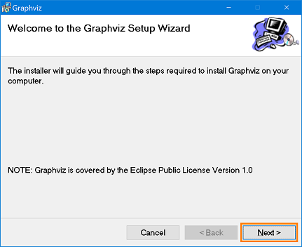
- Launch the installer and click the [Next] button.
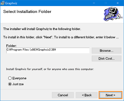
- Change the installation folder as desired, and click the [Next] button.
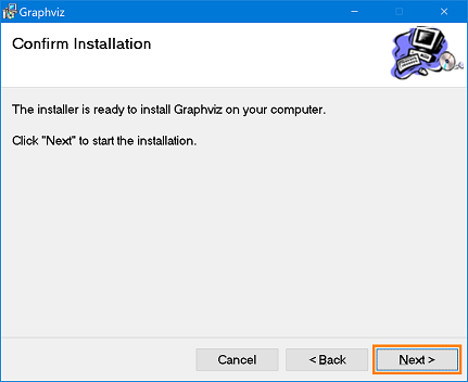
- Click the [Next] button to start the installation.
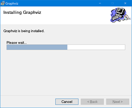
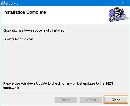
- After installation is completed, click the [Close] button.
Since installing from + msi does not pass through the path, you need to manually add the path to the environment variable. Right-click on the command prompt and select Run as administrator.
- Execute by entering the following command at the command prompt. > setx /M PATH "%PATH%;[installation folder path]"
If succeeded, "Success: specified value has been saved" is displayed.
- Close the command prompt and reopen it again.
- To check whether each command of Graphviz can be used, enter the following command.
>dot -V
バージョンが表示されれば完了となります。
It will be completed if version is displayed.
(G)Linux environment
You can install the necessary packages with the script used to install OpenRTM - aist.
| pkg_install_ubuntu.sh pkg_install_debian.sh pkg_install_fedora.sh pkg_install_raspbian.sh |
$ sudo sh pkg_install_***.sh -l c++ -l python -c --yes |
(G)Mass Installation
Please see Ubuntu, Debian, Fedora, Raspbian's The batch installation procedure is here.
(G)Common settings on Windows/Linux
(G)Installer package name
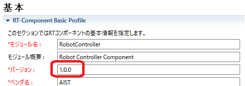
For Windows, it consists of "RTC project name + RTC version number_OpenRTM-aist version number_ architecture". The version number is a format without the dot, [1.0.0] is [100].
For Linux, it consists of "RTC project name _RTC version number _ architecture".
- Project name: RobotController
- Version number: 1.0.0
- Version of OpenRTM-aist: 1.2.0
- For Windows
- 32bit:RobotController100_rtm120_win32.msi
- 64bit:RobotController100_rtm120_win64.msi
- For Ubuntu, Debian
- 32bit:robotcontroller_1.0.0_i386.deb
- 64bit:robotcontroller_1.0.0_amd64.deb
- For Fedora
- 32bit:RobotController-1.0.0-i686.rpm
- 64bit:RobotController-1.0.0-x86_64.rpm
"RTC version number" is the value specified on the "Basic" tab of RTC Builder.
(G)Specify the installation directory
By default, OpenRTM-aist is installed in the location where you install and run the created installer package. On Windows environment only, OpenRTM - aist GUI screen when installing, you can optionally change to installation location.
The default installation path is determined by the following conditions.- The path of OpenRTM-aist installed in the environment where the installer package was created
- RTC language
- When RTC is generated, the module category specified on the basic tab (default is Category)
An arbitrary character string input is possible for module category.
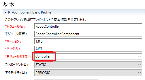
If this RTC is "C++", if you create an installer in an environment where OpenRTM - aist 1.2.0 32 - bit version is installed on Windows, the default installation destination is as follows.
C:\Program Files (x86)\OpenRTM-aist\1.2.0\Components\C++\Category\RobotController
When you create a package under Linux environment, the installation destination is as follows. In this example, the module category is "Controller".
/usr/share/openrtm-1.2/components/c++/Controller/RobotController
(G)Package Maintainer Information
The maintainer information of the package reflects the contents entered in "Creator/Contact" on RTC Builder's "Document Generation" tab. The form must be entered as "name <mail address>". The name must be written in Roman alphabet, and the e-mail address must be enclosed in < >. If it is blank, it will be "unknown". (Default is blank)
Create msi with CPack (Windows)
(G)Introduction
Build msi installer in Visual Studio and create it.
(G)Steps for creating without including doxygen document
By default, document build is not generated because it is OFF.
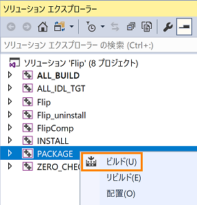
Right-click "PACKAGE" from the solution explorer of Visual Studio, select "Build" and execute.
(G)Steps for creating doxygen documents
Change the following line of CMakeLists.txt immediately under the project folder from OFF to ON.
In case of C++ RTC, it is around 86th row, and in Python RTC it is around 77th line.
option (BUILD_DOCUMENTATION "Build the documentation" ON) * Rewrite OFF in this line to ON. (Default is OFF)
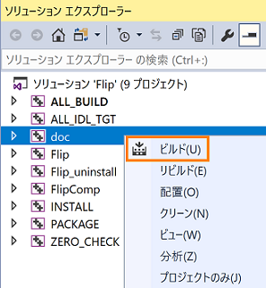
- Right-click "doc" from Solution Explorer of Visual Studio, select "Build" and execute.
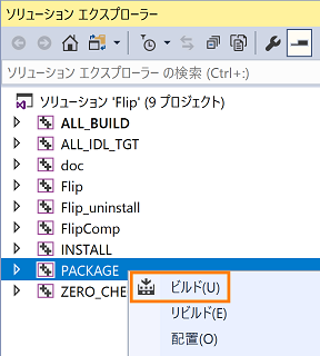
- After building with "doc", right click on "PACKAGE" and select "Build".
- Make sure "BUILD_DOCUMENTATION" is checked in CMake's configure.
- Build "doc" first, then build "PACKAGE". Build "PACKAGE" without building "doc" will result in an error.
(G)msi installer storage location, filename
If it succeeds, it is saved in [build] of the project directory.
The file name is "RTC project name + RTC version number_OpenRTM-aist version number_architecture".
(Example) Flip100_rtm120_win64.msi
(*) The architecture is [win32] or [win64].
The version number is a format without the dot, [1.0.0] is [100].
(G)Installing/Uninstalling msi
(G)Installation
- Double click on the created msi installer.
- Click the [Next] button.
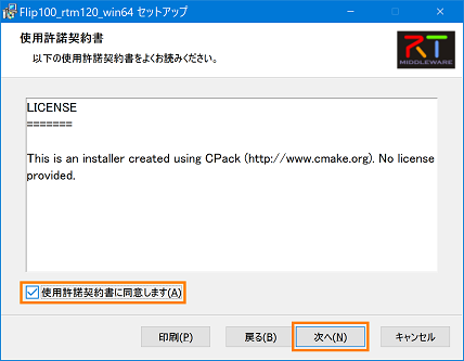
- Check [I agree to the license agreement] and click [Next].
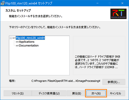
- Click the [Next] button.
The default installation path is as follows.
(Example) C:\Program Files\OpenRTM-aist\1.1.0\Components\c++\ImageProcessing\
ImageProcessing is the name specified in RTCBuilder's "module category"
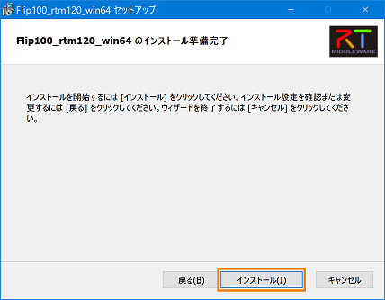
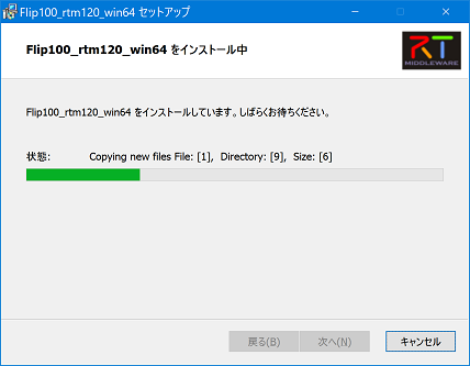
- Click [Install] to start the installation.
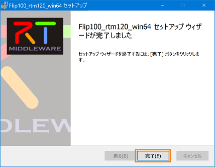
- Click [Finish] and exit the installer. After installation, it is registered in the start menu.
(G)GUID setting for upgrade
When upgrading, you need to set the GUID to check the already installed version. Since GUID is not set by default, a new GUID is assigned every time PACKAGE is built in Visual Studio. By setting the GUID in advance, it is possible to judge whether it is upgrade or new installation.The procedure for setting the GUID is as follows.
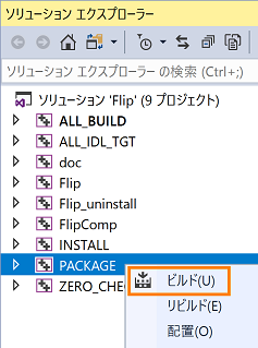
- Right-click "PACKAGE" from Solution Explorer in Visual Studio, select "Build" and execute.
- When the build is completed, the GUID is displayed on the following output screen, so select it and copy it.
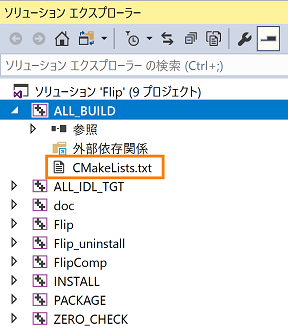
- Expand "ALL_BILD" from Solution Explorer and click CMakeLists.txt.
- Paste the GUID you copied in step 2 as shown below, overwrite and save CMakeLists.txt.
- Again, right-click "PACKAGE" from Solution Explorer, select "Build" and execute.
In addition to the above, you can also create a new GUID to create a GUID.
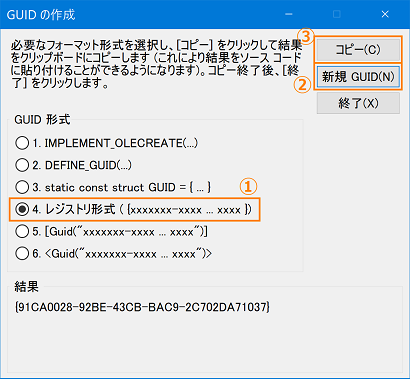
Select [Tools] > [Create GUID] from the Visual Studio menu to display the "Create GUID" dialog.
- In [GUID format], select [4. Registry format ...].
- Click the [New GUID] button.
- Click the [Copy] button.
- Click the [End] button to close the dialog.
- Paste it into CMakeLists.txt and overwrite it as shown in the screen below. *paste only numerals.
(G)Uninstall
Below is the uninstall procedure.(G)How to delete from the control panel
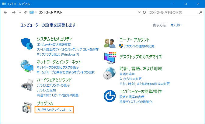
- Open [Control Panel] and click [Uninstall a program].
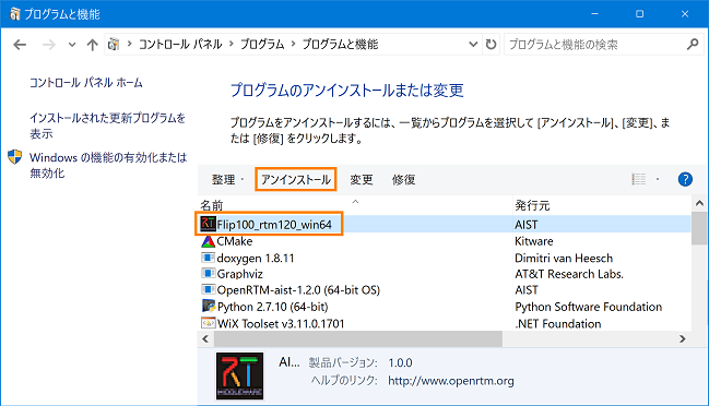
- Select the installed package name and click [Uninstall].
- Uninstallation is completed if the display disappears from the control panel list.
(G)How to delete from the installer
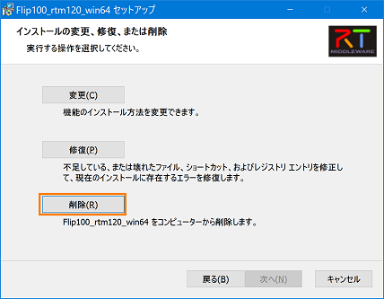
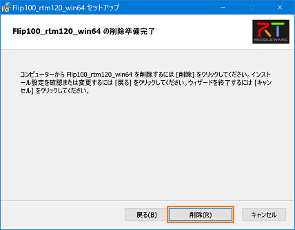
- Double click on the created msi installer.
- Click [Delete].
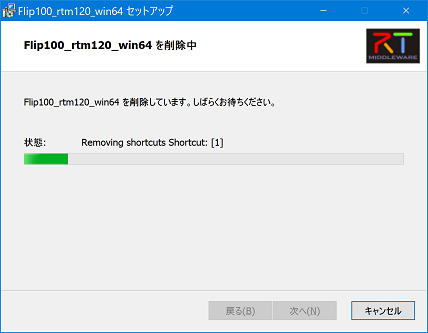
- Click [Delete].
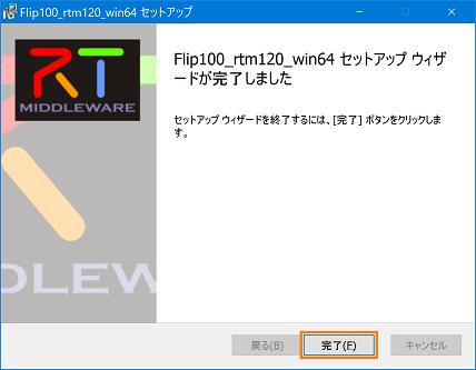
- Click [Finish] and exit the installer.
(G)IDL compilation process of Python RTC with service port
Python RTC with service port performs IDL compilation at package installation. Since this operation is realized by idlcompile.bat, delete.bat in the project folder when IDL compilation is executed, it is necessary to note that if these files are deleted, they will not function.
By uninstalling from the control panel, files created after IDL compilation are also deleted.
Below is a list of files installed by msi installer. ★ A file is generated by IDL compilation.
 tree /f installation directory\OpenRTM-aist\1.1.0\Components\Python\Category\FlipGUI
 C:\installation directory\OpenRTM-aist\1.1.0\Components\Python\Category\FlipGUI
 │  BasicDataType_idl.py ★
 │  CalibrationService_idl.py ★
 │  delete.bat
 │  ExtendedDataTypes_idl.py ★
 │  idlcompile.bat
 │  InterfaceDataTypes_idl.py ★
 │  RTC.xml
 │  rtutil.py
 │  setup.py
 │  flipgui.py
 │  FlipGUIComp.py
 │
 ├─idl
 │   BasicDataType.idl
 │   CalibrationService.idl
 │   CMakeLists.txt
 │   ExtendedDataTypes.idl
 │   InterfaceDataTypes.idl
 │
 ├─ImageCalibService ★
 │   __init__.py ★
 │
 ├─ImageCalibService__POA ★
 │   __init__.py ★
 │
 ├─RTC ★
 │   __init__.py ★
 │
 └─RTC__POA ★
__init__.py ★Create deb with CPack (Linux)
(G)Introduction
The following shows how to create a deb package.
(G)Steps for creating without including doxygen document
By default, document build is not generated because it is OFF.
- For C++ RTC
 $ cd project directory
 $ mkdir build
 $ cd build
 $ cmake ..
 $ make
 $ cpack
- For Python RTC
 $ cd project directory
 $ mkdir build
 $ cd build
 $ cmake ..
 $ cpack
(G)Steps for creating doxygen documents
Change the following line of CMakeLists.txt immediately under the project directory from OFF to ON.
In case of C ++ RTC, it is around 86th row, and in Python RTC it is around 77th line.
option(BUILD_DOCUMENTATION "Build the documentation" ON) (*) Rewrite this line OFF to ON. (Default is OFF)
- For C++ RTC
 $ cd project directory
 $ mkdir build
 $ cd build
 $ cmake ..
 $ make
 $ make doc
 $ cpack
- For Python RTC
 $ cd project directory
 $ mkdir build
 $ cd build
 $ cmake ..
 $ make doc
 $ cpack
【Notes】
If you turn on document build and execute "cpack" without "make doc", the following error occurs.
CMake Error at /home/project directory/build/doc/cmake_install.cmake: 36 (file):
(G)deb Save package location, file name
If it succeeds, it is saved in [build] of the project directory.
The file name is "RTC project name_RTC version number_architecture".
(Example) Flip_1.2.0_amd64.deb
(*)The architecture is [i386] or [amd64].
(G)How to check deb package
- When confirming the deb package with the less command
 $ cd project directory/build
 $ less Flip_1.2.0_amd64.deb
 Flip_1.2.0_amd64.deb
 New format debian package, version 2.0.
 Size 258304 bytes: Control archive = 2797 bytes.
     162 bytes,    9 rows      control
   10062 bytes,   92 rows      md5sums
 Package: affine
 Version: 1.2.0
 Section: devel
 Priority: optional
 Architecture: amd64
 Installed-Size: 884
 Maintainer: unknown (*)If package maintainer information is not defined, it will be "unknown"
 Description: Flip image component
To exit less, press "q".
- When extracting and checking contents of deb package
If the tree command is not installed, install it.
$ sudo apt-get install tree
 $ cd project directory/build
 $ dpkg -x Flip_1.2.0_amd64.deb .
 $ tree usr
 usr
 └─ share
     └─ openrtm-1.2
          └─ components
               └─ python
                    └─ Category (*)Specified installation directory
                         └─ FlipGUI
                              ├─ RTC.xml
                              ├─ FlipGUIComp.py
                              ├─ idl
                              │    ├─ BasicDataType.idl
                              │    ├─ CMakeLists.txt
                              │    ├─ CalibrationService.idl
                              │    ├─ ExtendedDataTypes.idl
                              │    └─ InterfaceDataTypes.idl
                              ├─ idlcompile.sh
                              ├─ rtutil.py
                              ├─ setup.py
                              └─ flipgui.py
(G)Install/Uninstall deb package
(G)Installation
Installation executes the following command.
 $ cd project directory/build
 $ sudo dpkg -i Flip_1.2.0_amd64.deb
(G)Uninstall
To uninstall, execute the following command.
$ sudo dpkg -r Flip
(G)IDL compilation process of Python RTC with service port
Python RTC with service port performs IDL compilation at package installation. Before IDL compilation is executed, postinst.in and prerm.in in the project directory realize this behavior, so be careful as deleting these files will not work. & br; & br; Below is a list of files installed from the deb package. ★ A file is generated by IDL compilation.
 $ tree /usr/share/openrtm-1.2/components/python/Category/FlipGUI/
 /usr/share/openrtm-1.2/components/python/Category/FlipGUI/
   ├─ BasicDataType_idl.py  ★
   ├─ CalibrationService_idl.py  ★
   ├─ ExtendedDataTypes_idl.py  ★
   ├─ ImageCalibService  ★
   │   └─ __init__.py  ★
   ├─ ImageCalibService__POA  ★
   │   └─ __init__.py  ★
   ├─ InterfaceDataTypes_idl.py  ★
   ├─ RTC  ★
   │   └─ __init__.py  ★
   ├─ RTC.xml
   ├─ RTC__POA  ★
   │   └─ __init__.py  ★
   ├─ FlipGUIComp.py
   ├─ idl
   │   ├─ BasicDataType.idl
   │   ├─ CMakeLists.txt
   │   ├─ CalibrationService.idl
   │   ├─ ExtendedDataTypes.idl
   │   └─ InterfaceDataTypes.idl
   ├─ idlcompile.sh
   ├─ rtutil.py
   ├─ setup.py
   └─ flipgui.py
Create rpm with CPack (Linux)
(G)Introduction
The following shows how to create an rpm package.
(G)Steps for creating without including doxygen document
(*)By default, document build is not generated because it is OFF.
- For C++ RTC
 $ cd Project directory
 $ mkdir build
 $ cd build
 $ cmake ..
 $ make
 $ cpack
- For Python RTC
 $ cd Project directory
 $ mkdir build
 $ cd build
 $ cmake ..
 $ cpack
(G)Steps for creating doxygen documents
Change the following line of CMakeLists.txt immediately under the project directory from OFF to ON.
In case of C++ RTC, it is around 86th row, and in Python RTC it is around 77th line.
option (BUILD_DOCUMENTATION "Build the documentation" ON) (*)Rewrite OFF in this line to ON. (Default is OFF)
- For C++ RTC
 $ cd Project directory
 $ mkdir build
 $ cd build
 $ cmake ..
 $ make
 $ make doc
 $ cpack
- For Python RTC
 $ cd Project directory
 $ mkdir build
 $ cd build
 $ cmake ..
 $ make doc
 $ cpack
【Notes】
If you turn on document build and execute "cpack" without "make doc", the following error occurs.
 CMake Error at /home/<Project directory>/build/doc/cmake_install.cmake:36 (file):
 file INSTALL cannot find
 "/home/<Project directory>/build/doc/html/doxygen/html".
(G)rpm package storage location, filename
If it succeeds, it is saved in [build] in the project directory.
The file name is "RTC project name-RTC version number-architecture".
(Example) Flip-1.2.0-x86_64.rpm
(*) The architecture is [i686] or [x86_64].
(G)How to check rpm package
- When confirming rpm package with less command
 $ cd <Project directory>/build
 $ less Flip-1.2.0-x86_64.rpm
 Name        : Flip
 Version     : 1.2.0
 Release     : 1
 Architecture: x86_64
 Install Date: (not installed)
 Group       : unknown
 Size        : 506080
 License     : unknown
 Signature   : (none)
 Source RPM  : Flip-1.2.0-1.src.rpm
 Build Date  : 2017 xxmonth xxdays xxhours xxminutes xxseconds
 Build Host  : localhost
 Relocations : /usr
 Vendor      : AIST
 Summary     : Flip image component
 Description :
 DESCRIPTION
To exit less, press "q".
- When extracting and checking the contents of rpm package
If the tree command is not installed, install it.
$ sudo apt-get install tree
 $ cd <Project directory>/build
 $ dpkg -x Flip-1.2.0-x86_64.rpm .
 $ tree usr
 usr
 └─ share
     └─ openrtm-1.2
          └─ components
               └─ python
                    └─ Category (*)Specified installation directory
                         └─ FlipGUI
                              ├─ RTC.xml
                              ├─ FlipGUIComp.py
                              ├─ idl
                              │    ├─ BasicDataType.idl
                              │    ├─ CMakeLists.txt
                              │    ├─ CalibrationService.idl
                              │    ├─ ExtendedDataTypes.idl
                              │    └─ InterfaceDataTypes.idl
                              ├─ idlcompile.sh
                              ├─ rtutil.py
                              ├─ setup.py
                              └─ flipgui.py
(G)Installation/Uninstallation of rpm package
(G)Installation
Installation executes the following command.
 $ cd <Project directory>/build
 $ sudo rpm -i Flip-1.2.0-x86_64.rpm
(G)Uninstall
To uninstall, execute the following command.
$ sudo rpm -e Flip
(G)IDL compilation process of Python RTC with service port
Python RTC with service port performs IDL compilation at package installation. Before IDL compilation is executed, postinst.in and prerm.in in the project directory realize this behavior, so be careful as deleting these files will not work.
Below is a list of files installed from rpm package. ★ A file is generated by IDL compilation.
 $ tree /usr/share/openrtm-1.2/components/python/Category/FlipGUI/
 /usr/share/openrtm-1.2/components/python/Category/FlipGUI/
  ├─ BasicDataType_idl.py  ★
  ├─ CalibrationService_idl.py  ★
  ├─ ExtendedDataTypes_idl.py  ★
  ├─ ImageCalibService  ★
  │   └─ __init__.py  ★
  ├─ ImageCalibService__POA  ★
  │   └─ __init__.py  ★
  ├─ InterfaceDataTypes_idl.py  ★
  ├─ RTC  ★
  │   └─ __init__.py  ★
  ├─ RTC.xml
  ├─ RTC__POA  ★
  │   └─ __init__.py  ★
  ├─ FlipGUIComp.py
  ├─ idl
  │   ├─ BasicDataType.idl
  │   ├─ CMakeLists.txt
  │   ├─ CalibrationService.idl
  │   ├─ ExtendedDataTypes.idl
  │   └─ InterfaceDataTypes.idl
  ├─ idlcompile.sh
  ├─ rtutil.py
  ├─ setup.py
  └─ flipgui.py
Other
(G)Other
(G)Acknowledgments
RTCBuilder was developed using the following library or product. Thanks to those involved in the development and design of these projects.- Apache Velocity 1.5 ~Copyright (C) 2000-2007 The Apache Software Foundation This product includes software developed by The Apache Software Foundation ( http://www.apache.org/ ).
- Apache Jakarta Commons CLI 1.1 ~Copyright 2001-2007 The Apache Software Foundation This product includes software developed by The Apache Software Foundation ( http://www.apache.org/ ).
- JYaml 1.3 ~Copyright (c) 2005, Yu Cheung Ho All rights reserved.
- Java CC (I use the generated source code) https://javacc.dev.java.net/
