LEGO Mindstorm NXT RT component
LEGO Mindstorms NXT RT-Component
LEGO Mindstorms NXT is a collection of LEGO components for creating robots. It includes 3 motors, 4 types of sensor and an intelligent brick, the NXT brick, for connecting and controlling them. NXT is connected via USB or Bluetooth to a PC, from which it can be directly controlled and programmed. It can also be loaded with user-created programs for operation independent of a PC.
This article will describe how to create an RT-Component (RTC) for the intelligent brick on a PC and, using other components, control connected motors and read connected sensors. With a single component for the NXT brick, controlling motors and reading sensors using existing RT-Components is simple.
Preparing SD Card
はじめに
ここでは、LEGO Mindstorms EV3 上で OpenRTM-aist とそのコンポーネントを動作させるための実行環境のインストールについて説明します。
ここでは、openrtm.org が提供する OpenRTM-aist 入りの OSイメージをダウンロードし、各種セットアップについて説明します。 EV3上で OpenRTM を使用できるようにするまでの大まかな手順は以下の通りです。
- SDカードに OSイメージを書き込む
- OS の基本的なセットアップ
- コンポーネントの実行テスト
SD カード
EV3 には micro SD カードスロットが一つあり、ここに起動した OS を書き込んだ micro SD カードを差し込むと、任意の OS を起動することができます。
用意する SDカードは 2GB以上 32GB以下のも micro SDカード になります。mini SD や SDカードは刺さりませんのでご注意ください。 また、書き込むイメージは約2GB程度ありますので、最低で2GBの容量が必要となります。EV3 は 32GBより大きい SDXC仕様の SDカードには対応していませんので、注意してください。
- 用意するSDカード
- micro SDカード
- 2GB以上、32GB以下
OSイメージのダウンロード
EV3上 での OpenRTM-aist の実行には ev3dev という OS を使用します。
- ev3dev Webページ: http://www.ev3dev.org
以下のサイトから ev3-ev3dev-jessie-2015-12-30.img.zip をダウンロードしてください。 名前が似たファイルが多数配布されているので間違えないようにしてください。
ev3dev OSイメージのダウンロード
ev3dev とは EV3 上で Linux のディストリビューションの1つである、Debian GNU Linuxを EV3 に搭載した EV3用の Debian ディストリビューションです。 OpenRTM-aist を動作させるには、この ev3dev を micro SDカードに書き込み、EV3 を SDカードから起動させます。
上記の ev3dev オフィシャルWebページから ev3dev の OSイメージファイルがダウンロードできますが、OpenRTM-aist などはインストールされていません。 基本的には、以下のリンクから OpenRTM-aist (C++、Python) 入りの ev3dev イメージファイルをダウンロードしてください。
サンプルコンポーネント入りのイメージ
Educator Vehicle等のサンプルコンポーネント入りのイメージです。
EV3の無線LANアダプタを交換した場合に、無線LANアクセスポイントモードが正常に動作しない場合があります。 その場合は他のアクセスポイントに接続する等して、以下のコマンドを実行して70-persistent-net.rulesを編集します。 ユーザー名はrobot、パスワードはmakerでログインして操作してください。
sudo nano /etc/udev/rules.d/70-persistent-net.rules
具体的には70-persistent-net.rulesのSUBSYSTEMから始まる行を全てコメントアウトします。
 # USB device 0x:0x (rtl8192cu)
 SUBSYSTEM=="net", ACTION=="add", DRIVERS=="?*", ATTR{address}=="00:22:cf:f6:52:a5", ATTR{dev_id}=="0x0", ATTR{type}=="1", KERNEL=="wlan*", NAME="wlan1"
イメージの展開
ダウンロードしたファイル YYYY-MM-DD-ev3dev-openrtm.zip を展開してください。 YYYY-MM-DD-ev3dev-openrtm.img という2GB位のファイルが展開されているはずです。
Windows
ファイルを右クリックして「すべて展開」を選択すると、展開できます。
Linux
$ unzip <イメージファイル>
で展開できます。unzip コマンドがない場合はインストールしてください。
 $ unzip 2015-08-06-ev3dev-openrtm.zip
 Archive:  2015-08-06-ev3dev-openrtm.zip
   inflating: 2015-08-06-ev3dev-openrtm.img
 $ ls -l
 合計 2321300
 -rw-rw-r-- 1 n-ando n-ando 1887436800  8月  4 21:37 2015-08-06-ev3dev-openrtm.img
 -rw-rw-r-- 1 n-ando n-ando  489565916  8月  5 10:13 2015-08-06-ev3dev-openrtm.zip
うまく展開できない場合、ダウンロードに失敗しファイルが壊れている可能性があります。壊れたファイルを削除して、再度ダウンロードしてみてください。
イメージの書き込み
展開された yyyy-mm-dd-ev3dev-openrtm.img はイメージファイルといい、ev3dev が起動するディスクの状態をディスクの最初から最後まで1バイトづつ抜き出したものです。 このファイルを SDカードに単純にコピーしても使用することはできません!!
以下に説明する方法で SDカードに書き込んでください。
イメージの書き込み (Windows)
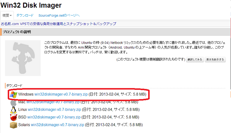
Windows では Win32DiskImager というツールを使用することでイメージの書き込みができます。 以下のサイトからイメージデータ書き込みツール Win32DiskImager のバイナリをダウンロードします。
- Win32DiskImager: http://sourceforge.jp/projects/sfnet_win32diskimager/ Win32DiskImager のダウンロード
ダウンロードしたファイル (win32diskimager-vX.X-binary.zip ) を解凍します。
※Win32DiskImager は、2バイト文字に対応していないため、YYYY-MM-DD-ev3dev-openrtm.zip は途中のパス名に全角文字や空白が含まれていない場所に解凍してください。
Raspberry Pi で使用する SD カードを PCに挿入し、Win32DiskImager を起動します。
※SD カードはドライブとして認識されている必要があるので、事前に FAT32 形式でフォーマットしておいてください。
「Image File」に解凍したRaspbian のイメージファイル (YYYY-MM-DD-wheezy-raspbian.img)、「Drive」にSD カードのドライブを指定し、「Write」ボタンをクリックします。
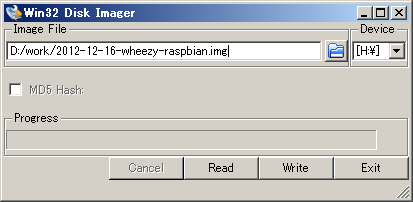
以上で SD カードの準備は終了です。 書き込みが終了したら、SD カードを Raspberry Pi に設置し、電源を投入します。
イメージの書き込み (Linux)
Linux では dd コマンドを利用してイメージの読み書きができます。 dd コマンドは UNIX系の OS なら大抵デフォルトでインストールされています。
SDカードを差し込んでから、 dmesg コマンドでカーネルのメッセージを確認します。
 $ dmesg
   : 中略
 [333478.822170] sd 3:0:0:0: [sdb] Assuming drive cache: write through
 [333478.822174]  sdb: sdb1 sdb2
 [333478.839563] sd 3:0:0:0: [sdb] Assuming drive cache: write through
 [333478.839567] sd 3:0:0:0: [sdb] Attached SCSI removable disk
 [333479.094873] EXT4-fs (sdb2): mounted filesystem with ordered data mode
 [333527.658195] usb 1-1: USB disconnect, address 2
このメッセージから SDカードのデバイス名を確認します。この例では sdb が SDカードのデバイス名のようです。/dev/の下を見てみます。
 ls -al /dev/sd*
 brw-rw---- 1 root disk 8,  0 May  7 17:28 /dev/sda
 brw-rw---- 1 root disk 8,  1 May  7 17:28 /dev/sda1
 brw-rw---- 1 root disk 8,  2 May  7 17:28 /dev/sda2
 brw-rw---- 1 root disk 8,  5 May  7 17:28 /dev/sda5
 brw-rw---- 1 root disk 8, 16 May 18 14:19 /dev/sdb
 brw-rw---- 1 root disk 8, 17 May 18 14:19 /dev/sdb1
 brw-rw---- 1 root disk 8, 32 May 18 14:19 /dev/sdc
sda は大抵システムディスクなので、絶対に触ってはいけません。
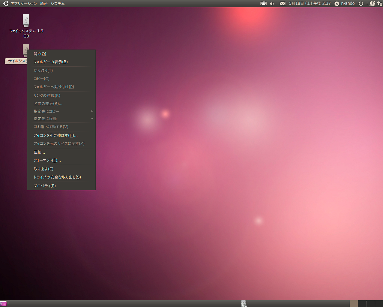
ディストリビューションによっては、SDカード内にマウント可能なファイルシステムがある場合自動でマウントするケースもあるようです。 その場合、ディスクをアンマウントしてください。(Ubuntuではデスクトップにマウントしたファイルシステムのフォルダーが現れるので右クリックで取り外してください。 それ以外は umount コマンドでアンマウントします。)
dd if=イメージファイル of=SDカードのデバイスファイル bs=1M のようにコマンドを入力し実行します。 ただし、デバイスファイルへの書き込みは管理者(root)権限が必要ですので、sudoを使用してください。
 $ sudo dd if=2015-08-05-ev3dev-openrtm.img of=/dev/sdb bs=1M
 1850+0 records in
 1850+0 records out
 1939865600 bytes (1.9 GB) copied, 201.543 s, 9.6 MB/s
実行中は別のターミナルなどで、iostat コマンドを実行して書き込みが正しく行われているかどうか見ることができます。 (最近のディストリビューションではデフォルトでインストールされていないことがあります。debian/ubuntu では apt-get install sysstat で iostatコマンドが使えるようになります。)
 $ iostat -mx 1
  avg-cpu:  %user   %nice %system %iowait  %steal   %idle
            0.00    0.00    0.00   50.25    0.00   49.75

 Device:         rrqm/s   wrqm/s     r/s     w/s    rMB/s    wMB/s avgrq-sz avgqu-sz   await  svctm  %util
 sda               0.00     0.00    0.00    1.00     0.00     0.00     8.00     0.00    0.00   0.00   0.00
 sdb               0.00  1856.00    0.00   78.00     0.00     9.14   240.00   143.40 1855.85  12.82 100.00
sdb の項目を見ると 9.14MB/s の書き込み速度が出ていることがわかります。 class 6 のSDカードなら 6MB/sec, class 10 の SDカードなら 10MB/sec 程度の速度が出ていれば、問題なく書き込まれていると考えてよいでしょう。 書き込みが終了すると、ディストリビューションによっては自動でマウントされる場合があります。その場合、アンマウントしてから SDカードを抜いてください。
イメージの書き込み (Mac OS X)
Mac OS X も Linuxと同様 dd コマンドを利用して書き込みます。 ただし、Mac では SDカードを挿入すると自動的にマウントされてしまい、マウント中は dd コマンドで SDカードに書き込むことができないので、アンマウント (OSから取り外す) する必要があります。
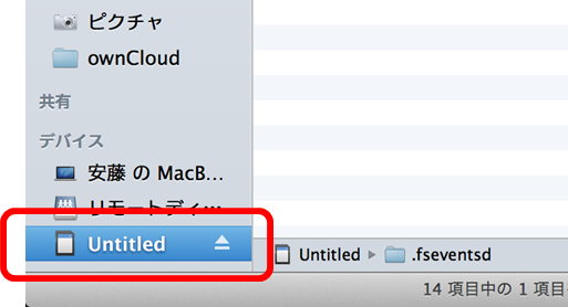
SDカードを差し込むとFinderに図のように SDカードのアイコンが現れます。 アンマウントするつもりでイジェクトボタンを押さないよう気を付けてください。
SDカードのボリューム名はここでは Untitled です。ボリューム名を覚えておきます。 コマンドプロンプトから df コマンドを入力すると以下のように表示されます。
 $ df -k
 Filesystem                        1024-blocks      Used Available Capacity   iused    ifree %iused  Mounted on
 /dev/disk0s2                        500000000 437664508  62079492    88% 109480125 15519873   88%   /
 devfs                                     194       194         0   100%       679        0  100%   /dev
 map -hosts                                  0         0         0   100%         0        0  100%   /net
 map auto_home                               0         0         0   100%         0        0  100%   /home
 /dev/disk1s1                            57288     18992     38296    34%       512        0  100%   /Volumes/Untitled
一番下 ''/Volumes/Untitled'' とあるのが先ほどの SDカードのマウントポイントです。一番左の SDカードのデバイス名 /dev/disk1s1 を覚えておきます。
 $ diskutil umount /Volumes/Untitled
 Volume (null) on disk1s1 unmounted
 $ df -k
 Filesystem                        1024-blocks      Used Available Capacity   iused    ifree %iused  Mounted on
 /dev/disk0s2                        500000000 437664716  62079284    88% 109480177 15519821   88%   /
 devfs                                     194       194         0   100%       679        0  100%   /dev
 map -hosts                                  0         0         0   100%         0        0  100%   /net
 map auto_home                               0         0         0   100%         0        0  100%   /home
先ほどの /Volumes/Untitled が消えて、SDカードがアンマウントされていることがわかります。 次に dd コマンドを使用してイメージを書き込みます。 dd if=イメージファイル of=/dev/rdisk1 bs=1m のように入力します。 of=/dev/rdisk1 は先ほど覚えたデバイスファイル /dev/disk1s1 のうち後ろの s1 を取り、さらに disk の前に raw deviceであることを示す r を付けたデバイス名です。
このコマンドはデバイスファイルにアクセスするので管理者 (root) でなければ実行できません。sudoを使用して以下のように実行します。
 $ sudo dd if=2015-08-05-ev3dev-openrtm.img of=/dev/rdisk1 bs=1m
 1850+0 records in
 1850+0 records out
 1939865600 bytes transferred in 302.377337 secs (6415380 bytes/sec)
 $
書き込み中は、「アクティビティモニタ」で「ディスクの動作」を見ることで書き込みが正しく行われているかどうかわかります。 class 6 の SDカードなら 6MB/sec, class 10のSDカードなら 10MB/sec 程度の速度が出ていれば、問題なく書き込まれていると考えてよいでしょう。
書き込みが終了すると、自動的に再度マウントされますので、今度は Finder のイジェクトボタンを押して SDカードを抜きます。
Mindstorms NXT Setup
Mindstorms NXT Setup
To create an RTC for the NXT, you must first setup your PC and NXT. The NXT can be connected to the PC by USB or Bluetooth, but because we don't want to tie our battery-powered, portable NXT to the PC with a cable, we will use Bluetooth.
Block assembly
Using the assembled robot shown in the photo as an example, we will create the NXT RTC.
This is a simple mobile base, called "Tribot," combined with a ultrasonic sensor (the "eyes") at the front. The Tribot construction instructions can be found in the NXT "Start Here" booklet included in the NXT kit. Attach the ultrasonic sensor to this base.
Bluetooth Device Installation
All revisions of the NXT intelligent brick include Bluetooth support. PCs without Bluetooth included can use USB Bluetooth adapters like those shown in the photo to communicate with the NXT. Install such a device if necessary, including any required device drivers. Most versions of Windows from XP SP2 on include suitable default device drivers.
Once a Bluetooth device has been installed, a "Bluetooth Devices" item should appear in the control panel. Clicking on this will produce the dialog shown below.
Select "Options," and enable device discovery and displaying the Bluetooth icon in the notification area. We will connect the NXT to the PC next, so leave this dialog open.
Connecting the NXT to the PC
The process to connect the NXT to the PC via Bluetooth is given below.
- Turn on the NXT
- Put the NXT into Bluetooth search mode
- Select your PC
- Select a channel
- Start the Connection Wizard from the Bluetooth Devices dialog on the PC
- Set a pass key
- Push the connect button on both the PC and NXT
- Restart the NXT once it has connected.
Starting the NXT
Press the central orange button on the NXT to turn on the power. A sequence of beeps will sound (if the volume is not set to zero) and the brick will turn on. The screen should look like the image below.
If it does not, use the square button below the orange button to navigate to the "My Files" mode.
Bluetooth Device Search
In "My Files" mode, press the triangular, grey buttons on either side of the orange button to move the cursor to the "Bluetooth" option, and press the orange button.
Use the grey buttons again to move the cursor to the "Search" option.
Press the orange button and a search for Bluetooth devices will be conducted. The screen will appear as below while searching.
Device Connection
If the PC has Bluetooth enabled and is visible to the NXT, the PC's name (as set in Windows) should appear on the screen of the NXT.
If other Bluetooth-enabled PCs are nearby, you may see more than one appear on the NXT. Use the triangular buttons to move the cursor to the correct PC name, then press the orange button. The channel selection screen will appear next. Press the orange button on the default selection. After displaying "Connecting" for a short time, the pass key input screen will appear. Press the orange button.
An information balloon should appear on the PC. Click on it to close it.
If the PC asks for a pass key, input the key that was displayed on the NXT. Once a connection is established, a dialog like that shown below will appear. To prevent other devices interfering, check "Disable discovery" before clicking "Finish."
Connection confirmation
Click on the "Devices" tab in the Bluetooth Devices dialog. The NXT should appear as below.
Installing NXT Python
Installing PyBlues
Download the Windows installer from the above link and run it.
Installing NXT Python
Download the zip file from the above link. NXT Python uses a setup.py script to install. If you have associated .py files with the Python interpreter, execute the script as follows from a command prompt:
setup.py install
c:\Python24\python setup.py install
 Microsoft Windows XP [Version 5.1.2600]
 (C) Copyright 1985-2001 Microsoft Corp.

 C:\tmp\nxt_python-0.7>setup.py install
 running install
 running build
 running build_py
 ...
 copying build\scripts-2.4\nxt_filer -> c:\python24\Scripts
 copying build\scripts-2.4\nxt_push -> c:\python24\Scripts
 copying build\scripts-2.4\nxt_test -> c:\python24\Scripts

 C:\tmp\nxt_python-0.7>
Test NXT Python
Turn on the NXT and connect it to the PC. Using the samples under example/, confirm that the NXT can be controlled from the PC.
The example/ directory contains the following samples:
- latency.py: Measures the latency in reading the sensors.
- mary.py: Plays "Mary Had a Little Lamb."
- message_test.py: Displays a message on the NXT's screen.
- spin.py: Spins motors connected to ports B and C.
- test_sensors.py: Displays all sensor values.
Motors and sensors must be connected appropriately for each test.
Making a NXT Python RTC
After completing the above preparations, the NXT should be controllable from the PC using Python.
At this point, you could use RtcTemplate to generate a NXT component template and get stuck in coding. However, while NXT Python is a clean module, please read on a little before putting NXT Python directly into an RT-Component.
As you can see from the samples, NXT Python is organised into modules for locators, motors, sensors, etc. In order to provide fine control over motors and sensors, the access method is a little complex.
We will create a class that allows us to access the many NXT Python modules through a single interface. We will use the Facade software pattern.
The facade pattern is a software engineering design pattern commonly used with Object-oriented programming. A facade is an object that provides a simplified interface to a larger body of code, such as a class library. (Source: "Facade pattern," Wikipedia)
Making such a class has the following benefits:
- Use it in places other than the RTC
- Easier to debug
- Debug the facade in isolation
- Debugging directly in the RTC makes it difficult to determine if a problem is because of the facade or the RTC.
- Modifications are easier
- Even if the facade class changes, if the interface does not change then the RTC component does not need to be changed.
- For example, if you want to add limits to some functions called get_xxx() and set_xxx(), this will only require changes in the facade.
- Easier to use devices other than the NXT
- For example, switching to a new version of the NXT that uses the same interface.
This is generally the case for RT-Components. Make good classes for robots and devices you wish to interact with, and even if the RTC itself changes or a new version is made, it will be easy to interact and maintenance will be greatly simplified.
Avoid creating low-level code like the following in your RTC's onExecute() method:
 ioctl(xxxx, xxxx); // UNIX direct device access
 inb(xxx);          // Direct I/O
 outb(xxx);         // Direct I/O
Ideally, create code like the following:
 onExecute(ec_id) { // Pseudocode
    if (m_inport.isNew()) {
       retval = m_myrobot.set_actuator(m_inport.read());
       if (retval == fatal_error) return RTC::RTC_ERROR;
    }
    if (myrobot.get_sensor(sensor_data) == true) {
       m_outport.write(sensor_data);
    } else {
       // Processing a read error
       if (fatal_error) return RTC::RTC_ERROR;
    }
    return RTC::RTC_OK;
 }
Code like this calls a function to process data from the input port and write sensor data to the output port. This sort of abstract code is ideal.
NXT Python Facade Class
NXT Python Facade Class
Nearly all functions of the NXT brick can be controlled using NXT Python. However, because utilising all functions is complex, the facade class will only focus on those functions we want to use. The main functions of the NXT are:
- Input
- Set motor speed
- Control the speaker
- Display messages
- Output
- Read motor encoder values
- Read sensors (microphone, ultrasonic, touch, light)
- Read system information
- Other
- Search for a NXT
- Connect to a NXT
- Read files from the NXT
- Read the NXT firmware
There is little meaning to putting all of these functions into the facade class. When another function is necessary, the facade can be extended to include it. In keeping with this, the facade described here will supply the functions necessary for the robot we will control.
- Input
- Set motor speed: setMotors()
- Output
- Read motor encoders: getMotors()
- Read sensors (microphone, ultrasonic, touch, light): getSensors()
A class made along these lines is shown below.
 #!/usr/bin/env python
 # @file NXTBrick.py
 # -*- coding:shift_jis -*-

 import nxt.locator
 from nxt.sensor import *
 from nxt.motor import *

 class NXTBrick:
     def __init__(self, bsock=None):
         """
         Constructor
         Connect to a NXT brick, control motors and sensors, and reset odometry.
         """
         if bsock:
             self.sock = bsock
         else:
             self.sock = nxt.locator.find_one_brick().connect()

         self.motors = [Motor(self.sock, PORT_A),
                        Motor(self.sock, PORT_B),
                        Motor(self.sock, PORT_C)]

         self.sensors = [TouchSensor(self.sock, PORT_1),
                         SoundSensor(self.sock, PORT_2),
                         LightSensor(self.sock, PORT_3),
                         UltrasonicSensor(self.sock, PORT_4)]
         self.resetPosition()

     def close(self):
         """
         Close the connection to the NXT.
         """
         self.sock.close()

     def resetPosition(self, relative = 0):
         """
         Reset the NXT motor encoders.
         """
         for m in self.motors:
             m.reset_position(relative)

     def setMotors(self, vels):
         """
         Receive an array, set the motor power levels.
         If the length of vels is not equal to the number of motors,
         the smaller of the two values is used.
         """
         for i, v in enumerate(vels[:min(len(vels),len(self.motors))]):
             self.motors[i].power = max(min(v,127),-127)
             self.motors[i].mode = MODE_MOTOR_ON | MODE_REGULATED
             self.motors[i].regulation_mode = REGULATION_MOTOR_SYNC
             self.motors[i].run_state = RUN_STATE_RUNNING
             self.motors[i].tacho_limit = 0
             self.motors[i].set_output_state()

     def getMotors(self):
         """
         Read the motor encoder angles.

         """
         state = []
         for m in self.motors:
             state.append(m.get_output_state())
         return state

     def getSensors(self):
         """
         Read the sensor values, return them in an array.
         """
         state = []
         for s in self.sensors:
             state.append(s.get_sample())
         return state


 """
 Test program
 Set a suitable motor value, read their encoders.
 Read sensor values and display them.
 """
 if __name__ == "__main__":
     import time
     nxt = NXTBrick()
     print "connected"

     # Motor test
     for i in range(100):
         nxt.setMotors([80,-80,80])
         print "Motor: "
         mstat = nxt.getMotors()
         for i, m in enumerate(mstat):
             print "(" , i, "): ", m
         time.sleep(0.1)
     nxt.setMotors([0,0,0])

     # Sensor test
     for i in range(100):
         sensors = ["Touch", "Sound", "Light", "USonic"]
         sval = nxt.getSensors()
         for s in sensors:
             print s + ": " + sval
             print ""
             time.speel(0.1)
The final section from if name == "main": is a test program. When this module is executed independently, the test will run. The module should be tested and corrected until it passes the test succesfully.
The above NXT facade class is very simple, only setting motor values, reading the encoders and reading the sensors. Trying to do everything from the start leads to a class whose purpose is difficult to understand. The class can be extended at any time, so begin with something simple that works as it should.
NXT RTC Implementation
NXT RTC Implementation
We shall now use the NXTBrick class created above to create an RTC.
- InPort
- Motor speed (TimedFloatSeq)
- Outport
- Motor position (TimedFloatSeq)
- Sensor data (TimedFloatSeq)
Generate NXTRTC base code
Generate the NXT RTC template
We shall use RtcTemplate to generate a template component. You can use the command line tool, rtc-template, or the Eclipse-based tool, RtcTemplate, to create the component.
If using rtc-template, make a batch file containing the following (remember to adjust paths as necessary):
 python "C:\Program Files\OpenRTM-aist\0.4\utils\rtc-template\rtc-template.py" -bpython^
  --module-name=NXTRTC --module-desc="NXT sample component"^
  --module-version=0.1 --module-vendor=AIST --module-category=example^
  --module-comp-type=DataFlowComponent --module-act-type=SPORADIC^
  --module-max-inst=10^
  --inport=vel:TimedFloatSeq^
  --outport=pos:TimedFloatSeq --outport=sens:TimedFloatSeq^
  --config="map:string:A,B"
Executing rtc-template using a created gen.bat:
 > gen.bat
  python "C:\Program Files\OpenRTM-aist\0.4\utils\rtc-template\rtc-template.py"
  -bpython --module-name=NXTRTC --module-desc="NXT sample component"
  --module-version=0.1 --module-vendor=AIST --module-category=example
  --module-comp-type=DataFlowComponent --module-act-type=SPORADIC
  --module-max-inst=10 --inport=vel:TimedFloatSeq
  --outport=pos:TimedFloatSeq --outport=sens:TimedFloatSeq
  --config="map:string:A,B"

   File "NXTRTC.py" was generated.
   File "README.NXTRTC" was generated.
   File "NXTRTC.yaml" was generated.
- Programing language selection: Python
- Module definition
- Module name: NXTRTC
- Module decription: NXT sample component
- Module version: 0.1
- Module vender: AIST
- Module category: example
- Component type: DataFlowComponent
- Component's activity type: SPORADIC
- Number of maximum instance: 10
- InPort definition
- Ports: Name:vel Type:TimedFloatSeq
- OutPort definition
- Ports: Name:pos, Type:TimedFloatSeq
- Ports: Name:sens, Type:TimedFloatSeq
- ConfigurationSet definition
- Cfg Sets: Name:map, Type:string, Default Value: A,B
Following these instructions should create the NXTRTC.py file containing the template component.
Sample code explanation
Sample code explanation
We will now add the NXTBrick.py functionality to the generated component.
- NXTBrick.py import: Import the NXTBrick.py file to get access to the NXTBrick class. The file extension is not necessary in the import statement.
import NXTBrick
- Implement onInitialize(self): In onInitialize(), instantiate the NXTBrick class. If this causes an error, return RTC_ERROR and the component will transition to the end state.
        # create NXTBrick object
        try:
            self._nxtbrick = NXTBrick.NXTBrick()
        except:
            print "NXTBrick create failed."""
            return RTC.RTC_ERROR
- Implement onActivated(self, ec_id) and onDeactivated(self, ec_id): In onActivated() and onDeactivated(), the NXTBrick class's resetPosition() method should be called.
self._nxtbrick.resetPosition()
- Implement onExecute(self, ec_id): The following steps should be performed by onExecute():
- Read speeds from the data InPort
- Based on configuration values, which port of the NXT the speed values are to be sent to should be set.
- Call the setMotors() method of the NXTBrick class to set motor speeds.
- Call the getSensors() method of the NXTBrick class to read the ultrasonic sensor data, and write this to an OutPort.
- Call the getMotors() method of the NXTBrick class to get the motor encoder angles, and write this to an OutPort.
Code that implements the above functionality is shown below:
 #!/usr/bin/env python
 # -*- coding:shift_jis -*-
 # -*- Python -*-

 import sys
 import time
 sys.path.append(".")

 # Import RTM module
 import OpenRTM
 import RTC


 # import NXTBrick class
 import NXTBrick


 # This module's spesification
 # <rtc-template block="module_spec">
 nxtrtc_spec = ["implementation_id", "NXTRTC",
          "type_name",         "NXTRTC",
          "description",       "NXT sample component",
          "version",           "0.1",
          "vendor",            "AIST",
          "category",          "example",
          "activity_type",     "DataFlowComponent",
          "max_instance",      "10",
          "language",          "Python",
          "lang_type",         "SCRIPT",
          "conf.default.map", "A,B",
          ""]

 # </rtc-template>

 class NXTRTC(OpenRTM.DataFlowComponentBase):
     def __init__(self, manager):
         OpenRTM.DataFlowComponentBase.__init__(self, manager)

         # DataPorts initialization
         # <rtc-template block="data_ports">
         self._d_vel = RTC.TimedFloatSeq(RTC.Time(0,0),[])
         self._velIn = OpenRTM.InPort("vel", self._d_vel, OpenRTM.RingBuffer(8))
         self.registerInPort("vel",self._velIn)
         self._d_pos = RTC.TimedFloatSeq(RTC.Time(0,0),[])
         self._posOut = OpenRTM.OutPort("pos", self._d_pos, OpenRTM.RingBuffer(8))
         self.registerOutPort("pos",self._posOut)
         self._d_sens = RTC.TimedFloatSeq(RTC.Time(0,0),[])
         self._sensOut = OpenRTM.OutPort("sens", self._d_sens, OpenRTM.RingBuffer(8))
         self.registerOutPort("sens",self._sensOut)

         # initialize of configuration-data.
         # <rtc-template block="configurations">
         self._map = [['A', 'B']]
         self._nxtbrick = None
         self._mapping = {'A':0,'B':1,'C':2}

     def onInitialize(self):
         # Bind variables and configuration variable
         # <rtc-template block="bind_config">
         self.bindParameter("map", self._map, "A,B")

         # create NXTBrick object
         try:
             print "Connecting to NXT brick ...."
             self._nxtbrick = NXTBrick.NXTBrick()
             print "Connection established."
         except:
             print "NXTBrick connection failed."
             return RTC.RTC_ERROR

         return RTC.RTC_OK

     def onFinalize(self):
         self._nxtbrick.close()


     def onActivated(self, ec_id):
         # reset NXTBrick's position.
         self._nxtbrick.resetPosition()

         return RTC.RTC_OK

     def onDeactivated(self, ec_id):
         # reset NXTBrick's position.
         self._nxtbrick.resetPosition()

         return RTC.RTC_OK

     def onExecute(self, ec_id):
         cnt = 0
         # check new data.
         if self._velIn.isNew():
             # read velocity data from inport.
             self._d_vel = self._velIn.read()
             vel_ = [0,0,0]
             vel_[self._mapping[self._map[0][0]]] = self._d_vel.data[0]
             vel_[self._mapping[self._map[0][1]]] = self._d_vel.data[1]
             # set velocity
             self._nxtbrick.setMotors(vel_)

         # get sensor data.
         sensor_   = self._nxtbrick.getSensors()
         if sensor_:
             self._d_sens.data = sensor_
             self._sensOut.write()

         # get position data.
         position_ = self._nxtbrick.getMotors()
         if position_:
             self._d_pos.data =                  [position_[self._mapping[self._map[0][0]]][9],                       position_[self._mapping[self._map[0][1]]][9]]
         # write position data to outport.
         self._posOut.write()

         return RTC.RTC_OK


 def MyModuleInit(manager):
     profile = OpenRTM.Properties(defaults_str=nxtrtc_spec)
     manager.registerFactory(profile,
                             NXTRTC,
                             OpenRTM.Delete)

     # Create a component
     comp = manager.createComponent("NXTRTC")


 def main():
     mgr = OpenRTM.Manager.init(len(sys.argv), sys.argv)
     #mgr = OpenRTM.Manager.init(sys.argv)
     mgr.setModuleInitProc(MyModuleInit)
     mgr.activateManager()
     mgr.runManager()

 if __name__ == "__main__":
     main()
Sample code explanation (Callback object usage example)
This sample code adds a callback, OnWrite, to the above sample. When data is written to the InPort's buffer, the motor's speeds will be set immediately.
- Callback class
Create a callback class as below.
 # @class CallBackClass
 # @brief callback class
 #
 # when data is written in the buffer of InPort,
 # it is called.
 class CallBackClass:
     def __init__(self, nxtbrick_, map_):
         self._nxtbrick = nxtbrick_
         self._map = map_
         self._mapping = {'A':0,'B':1,'C':2}

     def __call__(self, pData):
         vel_ = [0,0,0]
         vel_[self._mapping[self._map[0][0]]] = pData.data[0]
         vel_[self._mapping[self._map[0][1]]] = pData.data[1]
         # set velocity
         self._nxtbrick.setMotors(vel_)
This class receives a NXTBrick instance and a configuration parameter map in its constructor.
- Callback class registration
Use the setOnWrite() method to register a CallBackClass instance with the component.
   # set callback class
   self._velIn.setOnWrite(CallBackClass(self._ntxbrick,self._map))
After this call to setOnWrite(), whenever data is written to the InPort, CallBackClass.call() will be called.
Sample code that implements the complete component using a callback class is shown below.
 #!/usr/bin/env python
 # -*- coding:shift_jis -*-
 # -*- Python -*-

 import sys
 import time
 sys.path.append(".")

 # Import RTM module
 import OpenRTM
 import RTC


 # import NXTBrick class
 import NXTBrick


 # This module's spesification
 # <rtc-template block="module_spec">
 nxtrtc_spec = ["implementation_id", "NXTRTC",
          "type_name",         "NXTRTC",
          "description",       "NXT sample component",
          "version",           "0.1",
          "vendor",            "AIST",
          "category",          "example",
          "activity_type",     "DataFlowComponent",
          "max_instance",      "10",
          "language",          "Python",
          "lang_type",         "SCRIPT",
          "conf.default.map", "A,B",
          ""]

 # </rtc-template>

 # @class CallBackClass
 # @brief callback class
 #
 # when data is written in the buffer of InPort,
 # it is called.
 class CallBackClass:
     def __init__(self, nxtbrick_, map_):
         self._nxtbrick = nxtbrick_
         self._map = map_
         self._mapping = {'A':0,'B':1,'C':2}

     def __call__(self, pData):
         vel_ = [0,0,0]
         vel_[self._mapping[self._map[0][0]]] = pData.data[0]
         vel_[self._mapping[self._map[0][1]]] = pData.data[1]
         # set velocity
         self._nxtbrick.setMotors(vel_)


 class NXTRTC(OpenRTM.DataFlowComponentBase):
     def __init__(self, manager):
         OpenRTM.DataFlowComponentBase.__init__(self, manager)

         # DataPorts initialization
         # <rtc-template block="data_ports">
         self._d_vel = RTC.TimedFloatSeq(RTC.Time(0,0),[])
         self._velIn = OpenRTM.InPort("vel", self._d_vel, OpenRTM.RingBuffer(8))
         self.registerInPort("vel",self._velIn)
         self._d_pos = RTC.TimedFloatSeq(RTC.Time(0,0),[])
         self._posOut = OpenRTM.OutPort("pos", self._d_pos, OpenRTM.RingBuffer(8))
         self.registerOutPort("pos",self._posOut)
         self._d_sens = RTC.TimedFloatSeq(RTC.Time(0,0),[])
         self._sensOut = OpenRTM.OutPort("sens", self._d_sens, OpenRTM.RingBuffer(8))
         self.registerOutPort("sens",self._sensOut)

         # initialize of configuration-data.
         # <rtc-template block="configurations">
         self._map = [['A', 'B']]
         self._nxtbrick = None
         self._mapping = {'A':0,'B':1,'C':2}

     def onInitialize(self):
         # Bind variables and configuration variable
         # <rtc-template block="bind_config">
         self.bindParameter("map", self._map, "A,B")

         # create NXTBrick object
         try:
             print "Connecting to NXT brick ...."
             self._nxtbrick = NXTBrick.NXTBrick()
             print "Connection established."
         except:
             print "NXTBrick connection failed."
             return RTC.RTC_ERROR

         # set callback class
         self._velIn.setOnWrite(CallBackClass(self._ntxbrick,self._map))

         return RTC.RTC_OK

     def onFinalize(self):
         self._nxtbrick.close()

     def onActivated(self, ec_id):
         # reset NXTBrick's position.
         self._nxtbrick.resetPosition()

         return RTC.RTC_OK


     def onDeactivated(self, ec_id):
         # reset NXTBrick's position.
         self._nxtbrick.resetPosition()

         return RTC.RTC_OK


     def onExecute(self, ec_id):
         # get sensor data.
         sensor_   = self._nxtbrick.getSensors()
         if sensor_:
             self._d_sens.data = [sensor_[3]]
             # write sensor data to outport.
             self._sensOut.write()

         # get position data.
         position_ = self._nxtbrick.getMotors()
         if position_:
             self._d_pos.data = [position_[self._mapping[self._map[0][0]]][9],position_[self._mapping[self._map[0][1]]][9]]
             # write position data to outport.
             self._posOut.write()

         return RTC.RTC_OK


 def MyModuleInit(manager):
     profile = OpenRTM.Properties(defaults_str=nxtrtc_spec)
     manager.registerFactory(profile,
                             NXTRTC,
                             OpenRTM.Delete)

     # Create a component
     comp = manager.createComponent("NXTRTC")


 def main():
     mgr = OpenRTM.Manager.init(len(sys.argv), sys.argv)
     #mgr = OpenRTM.Manager.init(sys.argv)
     mgr.setModuleInitProc(MyModuleInit)
     mgr.activateManager()
     mgr.runManager()

 if __name__ == "__main__":
     main()
In the first example, the motor output, sensor reading and motor encoder reading are all done in a single synchronous loop. By using a callback, the motor output is done asynchronously when data arrives.
NXT RTC Test
We will now test our NXT RT-Component.
Start the name server
The name server must be started to connect components together. If you have installed the Windows C++ version of OpenRTM-aist, the Start Menu will contain an entry for this: OpenRTM-aist->C++->examples->Start Naming Service.
Write an rtc.conf file
Put the following into a file named "rtc.conf":
 corba.nameservers: localhost
 naming.formats: %n.rtc
- TkJoystickComp
- TkMotorPosComp
- TkSliderMonitorComp
Start RtcLink
Start RtcLink. Once it has started, connect to your name server and open the System Diagram Editor.
Start Components
Execute the following components:- NXTRTC
- TkJoystickComp
- TkMotorPosComp
- TkSliderMonitorComp As each is executed, it will appear in the name service view of RtcLink.
TkJoystickComp
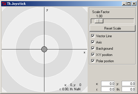
TkJoyStickComp is a graphical virtual joystick component (see image, below). The centre circle can be dragged like a joystick to send X/Y values out its upper OutPort. The lower OutPort outputs values suitable for controlling a differential drive robot, such as the Tribot.
TkMotorComp
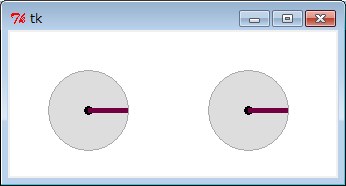
TkMotorComp is a GUI-based component for displaying motor angles received at its InPort. It can be used to monitor the rotation of wheels. Connect the angle output port of NXTRTC to its input port to display the angle of the Tribot's wheels. The angle will change even if you turn the wheels by hand.
TkSliderMonitorComp
This component displays values received at its input port in a GUI using sliders. Connect the sensor output of the NXTRTC component to it to monitor the NXT's sensor values.
Connect Components
After executing all components, we will connect them together. Drag each component from the name service view into the system diagram editor window. Click and drag between the ports you want to connect together. The screenshot below shows one example of connecting some components.
Using these components, confirm that the NXTRTC component functions correctly.
Make your own components to control the NXT brick
You have successfully made the NXT into an RT-Component. Now, make new components using your own logic to control the NXT. You can make new components using Python, C++ or Java. No matter what language you use, you can connect your new components with the NXTRTC component created here.
