
tutorial (raspberry pi mouse, c++, ubuntu, bootcamp edition)
✏️ Edit this page on GitHub#contents
Introduction
This page explains the procedure for creating a component to control a Raspberry Pi Mouse in the simulator.
Downloading the Materials
First, download the materials.
git clone https://github.com/OpenRTM/RTM_Tutorial_RaspberryPiMouse
Workshops may sometimes be conducted in environments without Internet access. In such cases, the files are included on the distributed USB memory.
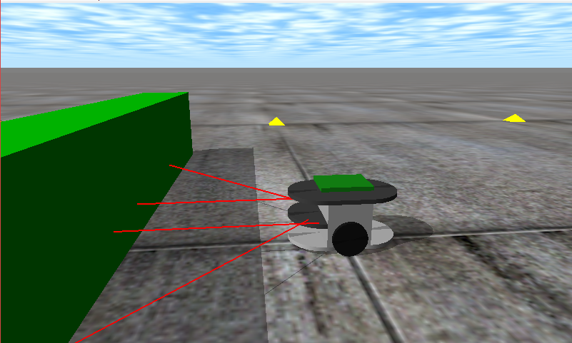
Simulator
The simulator was developed using the physics engine Open Dynamics Engine (ODE) and the drawing library (drawstuff) included with ODE.
Since it runs as long as OpenGL is available, it should work in most environments.
It can simulate the following robot, the Raspberry Pi Mouse.
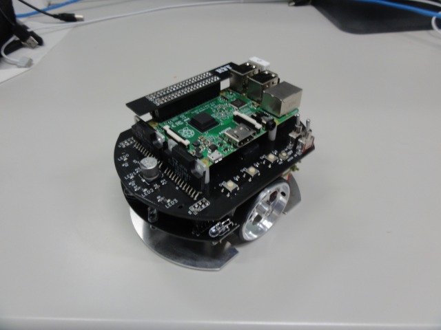
The simulator reproduces not only the dynamics calculations and contact responses of the Raspberry Pi Mouse, but also distance sensor data with values close to those of the actual robot.
Raspberry Pi Mouse Specifications
The Raspberry Pi Mouse is an independently driven two-wheel mobile robot sold by RT Corporation.
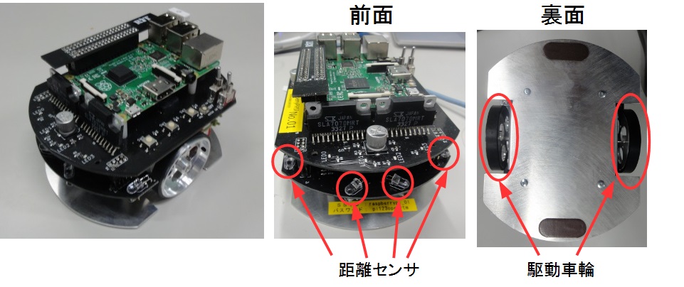
| Raspberry Pi Mouse Specifications | |
|---|---|
| CPU | Raspberry Pi 2 Model B |
| Motor | Two ST-42BYG020 Stepper Motors |
| Motor Driver | Two SLA7070MRPT Units |
| Distance Sensor | Four Red LEDs + Phototransistors (ST-1K3) |
| Red Indicator LED | 4 |
| Buzzer | 1 |
| Switch | 3 |
| Battery | One LiPo 3-cell (11.1V) 1000mAh Battery |
RT Component to Create
- RobotController Component
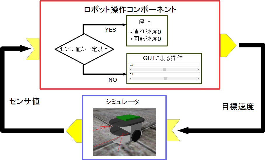
This component connects to the RaspberryPiMouseSimulator component and controls the robot in the simulator.
Creating the RobotController Component
In this tutorial, you will create a component that controls the robot in the simulator using a GUI (slider) and automatically stops when the sensor value exceeds a specified threshold.
Development Procedure
The development procedure is as follows.
- Verify the development environment
- Define the component specifications
- Generate template source code using RTC Builder
- Edit the source code
- Verify component operation
Operating Environment / Development Environment
The development environment is built on Linux (Ubuntu 18.04 is assumed in this tutorial).
Installing OpenRTM-aist
 ubuntu 18.04 (64bit)


 $ wget https://raw.githubusercontent.com/OpenRTM/OpenRTM-aist/master/scripts/pkg_install_ubuntu.sh
 $ sudo sh pkg_install_ubuntu.sh
Installing JRE
$ sudo apt-get install openjdk-8-jdk
For Ubuntu 18.04 and 18.10, switch to Java 8 using the following command.
$ sudo update-alternatives --config java
After starting Eclipse, RTSystemEditor may fail to connect to the Name Server. In that case, add your host name to the localhost entry in /etc/hosts.
 $ hostname
 ubuntu1804 ← The host name is ubuntu1804
 $ sudo vi /etc/hosts

 Change:
 127.0.0.1       localhost

 To:
 127.0.0.1       localhost ubuntu1404
Installing CMake
$ sudo apt-get install cmake cmake-gui
Installing Code::Blocks
Code::Blocks is an integrated development environment (IDE) that supports C/C++.
It can be installed using the following command.
$ sudo apt-get install codeblocks
If you want to install the latest version, run the following commands.
 $ sudo add-apt-repository ppa:damien-moore/codeblocks-stable
 $ sudo apt-get update
 $ sudo apt-get install codeblocks
Installing Premake
Premake is required for building ODE.
$ sudo apt-get install premake4
RaspberryPiMouseSimulator Component
The simulator component must be built manually.
Run the following commands.
 $ wget https://raw.githubusercontent.com/OpenRTM/RTM_Tutorial_RaspberryPiMouse/master/script/install_raspimouse_simulator.sh
 $ sh install_raspimouse_simulator.sh
Workshops may sometimes be conducted in environments without Internet access. In that case, run the script included on the distributed USB memory.
$ sh install_raspimouse_simulator_usb.sh
Component Specification
RobotController has an OutPort for outputting target velocity, an InPort for receiving sensor values, and configuration parameters for setting target velocity and the sensor threshold used for stopping.
| Component Name | RobotController |
|---|---|
| InPort | |
| Port Name | in |
| Type | TimedShortSeq |
| Description | Sensor Values |
| OutPort | |
| Port Name | out |
| Type | TimedVelocity2D |
| Description | Target Velocity |
| Configuration | |
| Parameter Name | speed_x |
| Type | double |
| Default Value | 0.0 |
| Constraint | -1.5<x<1.5 |
| Widget | slider |
| Step | 0.01 |
| Description | Forward Velocity Setting |
| Configuration | |
| Parameter Name | speed_r |
| Type | double |
| Default Value | 0.0 |
| Constraint | -2.0<x<2.0 |
| Widget | slider |
| Step | 0.01 |
| Description | Rotational Velocity Setting |
| Configuration | |
| Parameter Name | stop_d |
| Type | int |
| Default Value | 30 |
| Description | Sensor Value Threshold for Stopping |
About the TimedVelocity2D Type
The TimedVelocity2D type is used to store the velocity of a mobile robot moving on a two-dimensional plane.
     struct Velocity2D
     {
         /// Velocity along the x axis in metres per second.
         double vx;
         /// Velocity along the y axis in metres per second.
         double vy;
         /// Yaw velocity in radians per second.
         double va;
     };


     struct TimedVelocity2D
     {
         Time tm;
         Velocity2D data;
     };
This data type can store velocity along the X-axis (vx), velocity along the Y-axis (vy), and rotational velocity around the Z-axis (va).
vx, vy, and va represent velocities in the robot-centered coordinate system.
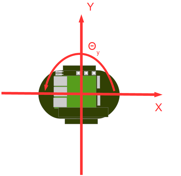
vx is the velocity in the X direction, vy is the velocity in the Y direction, and va is the angular velocity around the Z-axis.
For robots such as the Raspberry Pi Mouse, which have two wheels mounted on the left and right sides, vy is assumed to be 0 because the robot cannot move sideways without slipping.
The robot is controlled by specifying the forward velocity vx and the rotational velocity va.
About Distance Sensor Data
The Raspberry Pi Mouse distance sensors output larger values as an object gets closer.
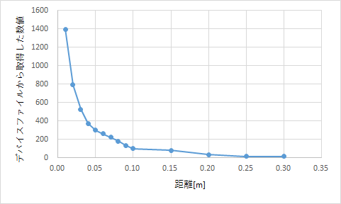
| Value Obtained from Device File | Actual Distance [m] |
|---|---|
| 1394 | 0.01 |
| 792 | 0.02 |
| 525 | 0.03 |
| 373 | 0.04 |
| 299 | 0.05 |
| 260 | 0.06 |
| 222 | 0.07 |
| 181 | 0.08 |
| 135 | 0.09 |
| 100 | 0.10 |
| 81 | 0.15 |
| 36 | 0.20 |
| 17 | 0.25 |
| 16 | 0.30 |
The simulator reproduces and outputs these values.
The RobotController component implements processing to automatically stop when these values exceed a specified threshold.
Generating the RobotController Component Template
The RobotController component template is generated using RTCBuilder.
Starting RTCBuilder
In Eclipse, the folder used for various work is called a “workspace” (Work Space), and in principle, all generated files are saved under this folder.
The workspace can be created in any accessible folder, but this tutorial assumes the following workspace.
- /home/username/workspace
First, start Eclipse.
Move to the directory where OpenRTP was extracted and enter the following command.
$ ./openrtp
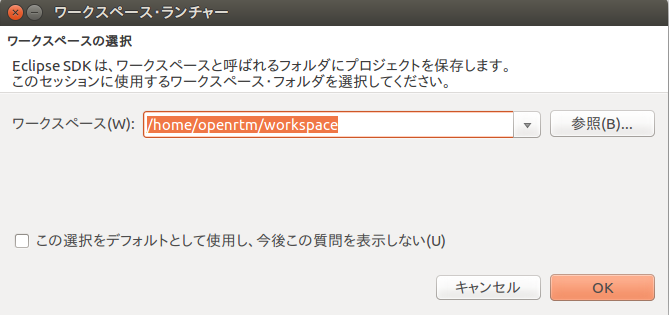
When prompted for the workspace location at startup, specify the workspace above.
The following Welcome page will then be displayed.
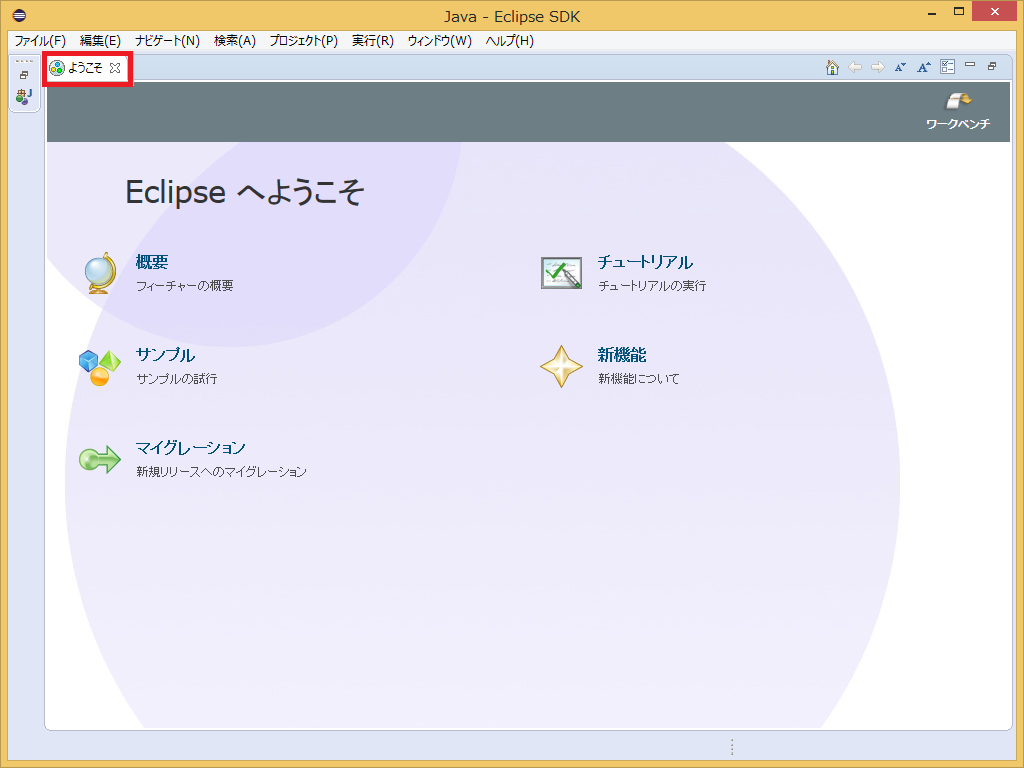
The Welcome page is not needed now, so click the “×” button in the upper-left corner to close it.
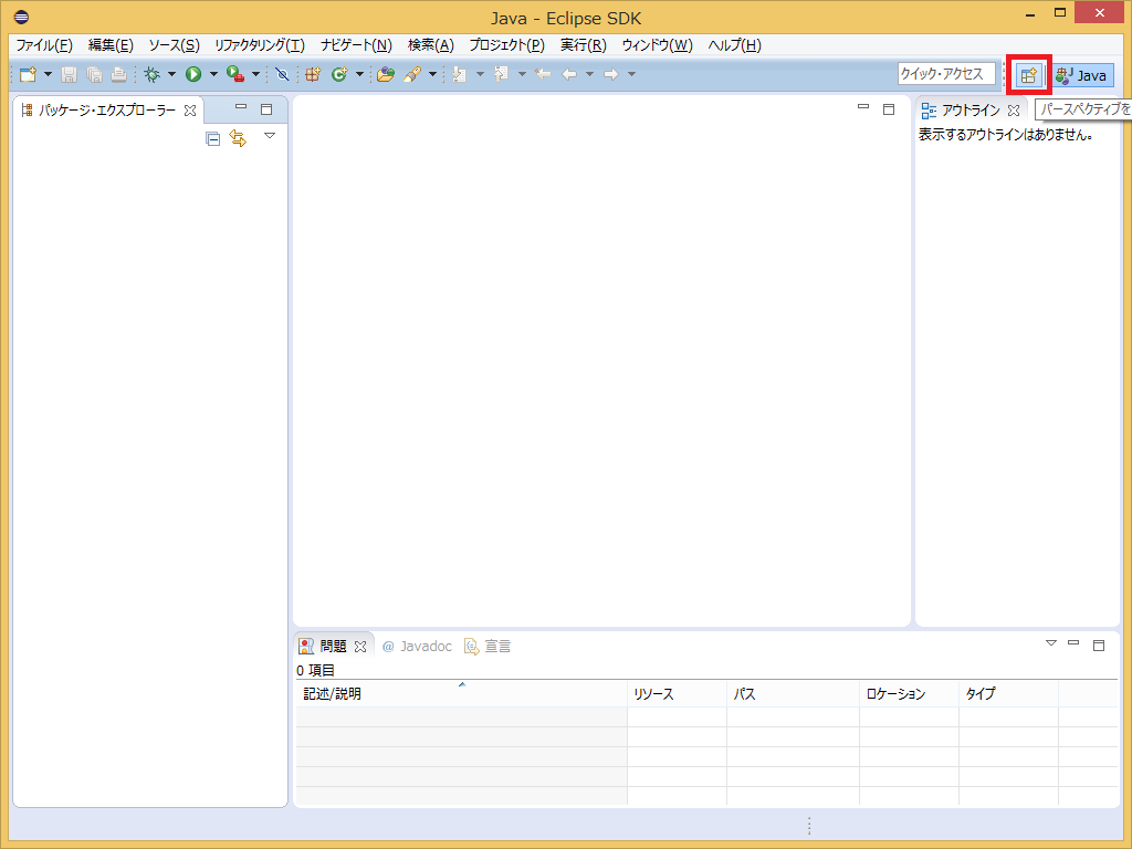
Click the [Open Perspective] button in the upper-right corner.
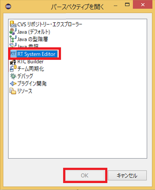
Select “RTC Builder” to start RTCBuilder. The RTCBuilder icon with a “hammer and RT” will appear in the menu bar.
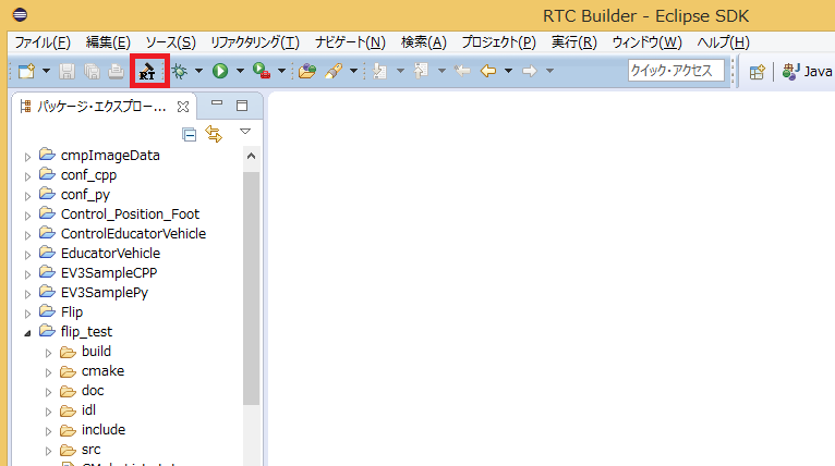
Creating a New Project
To create the RobotController component, you need to create a new project in RTC Builder.
Click the [Open New RTCBuilder Editor] icon in the upper-left corner.
Enter the project name to create (in this case, RobotController) in the “Project Name” field and click [Finish].
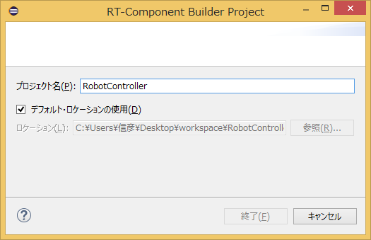
A project with the specified name will be generated and added to the Package Explorer.
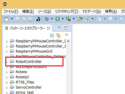
Within the generated project, an RTC profile XML (RTC.xml) with default values is automatically generated.
Starting the RTC Profile Editor
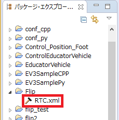
When RTC.xml is generated, the RTCBuilder editor associated with this project should open as part of the workspace.
If it does not start, double-click RTC.xml in the Package Explorer.
Entering Profile Information and Generating Code
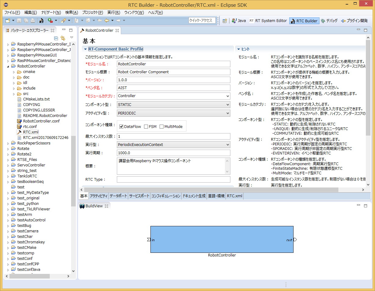
First, select the leftmost “Basic” tab and enter the basic information.
In addition to the RobotController component specification (name) defined earlier, enter the description, version, and other information.
Fields with red labels are required. All other fields can remain at their default values.
- Module Name: RobotController
- Module Description: Optional (Robot Controller component)
- Version: Optional (1.0.0)
- Vendor Name: Optional
- Module Category: Optional (Controller)
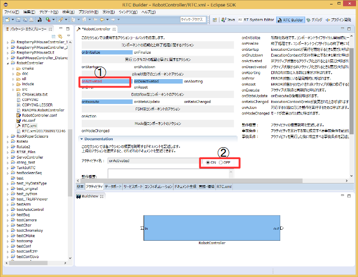
Next, select the “Activity” tab and specify the action callbacks to use.
The RobotController component uses the onActivated(), onDeactivated(), and onExecute() callbacks. As shown below, click onActivated (①), then check [ON] using the radio button (②).
Perform the same procedure for onDeactivated and onExecute.
Next, select the “Data Ports” tab and enter the data port information.
Enter the following based on the specifications defined earlier. The variable names and display positions are optional and may be left unchanged.
- InPort Profile:
- Port Name: in
- Data Type: TimedShortSeq
- OutPort Profile:
- Port Name: out
- Data Type: TimedVelocity2D
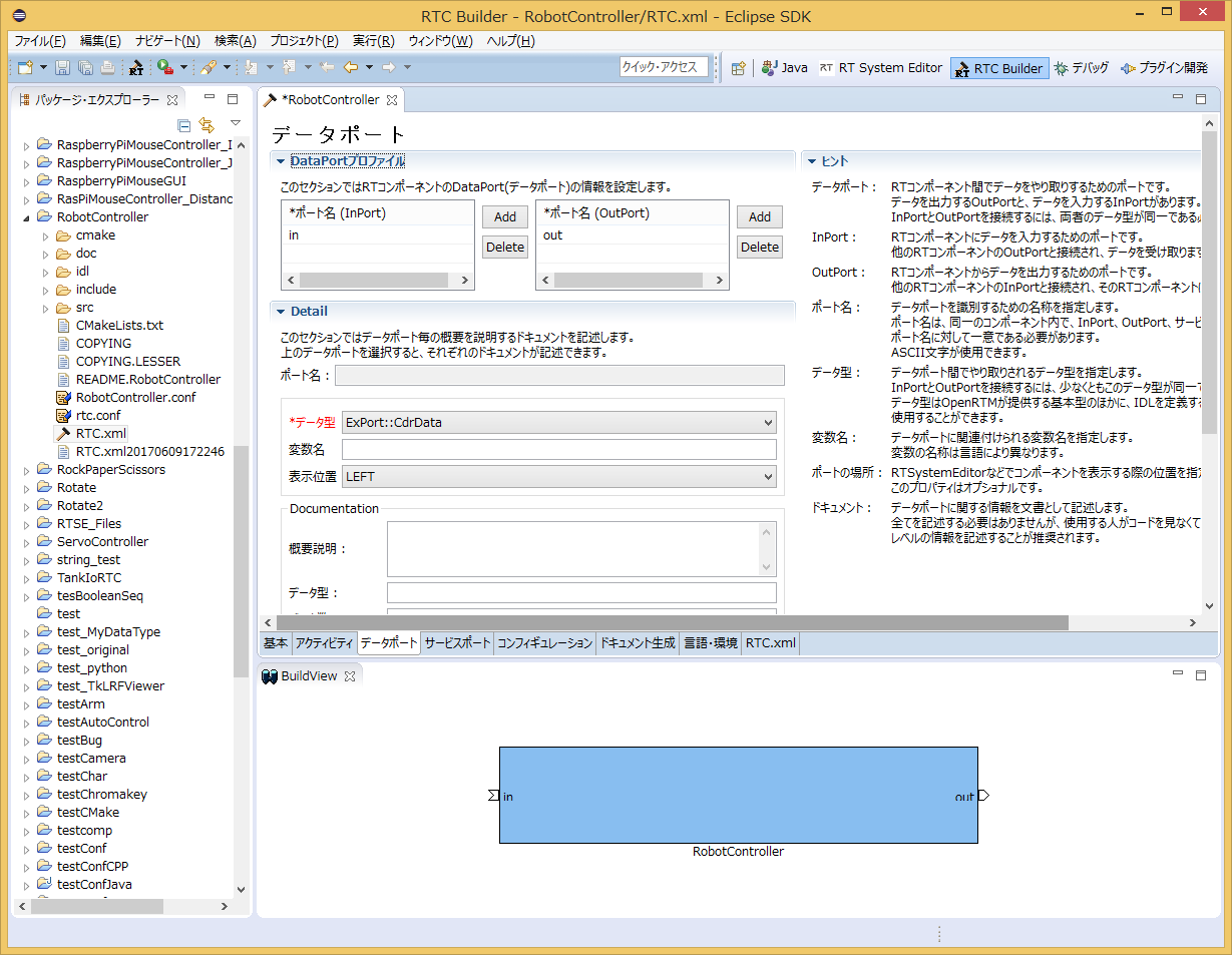
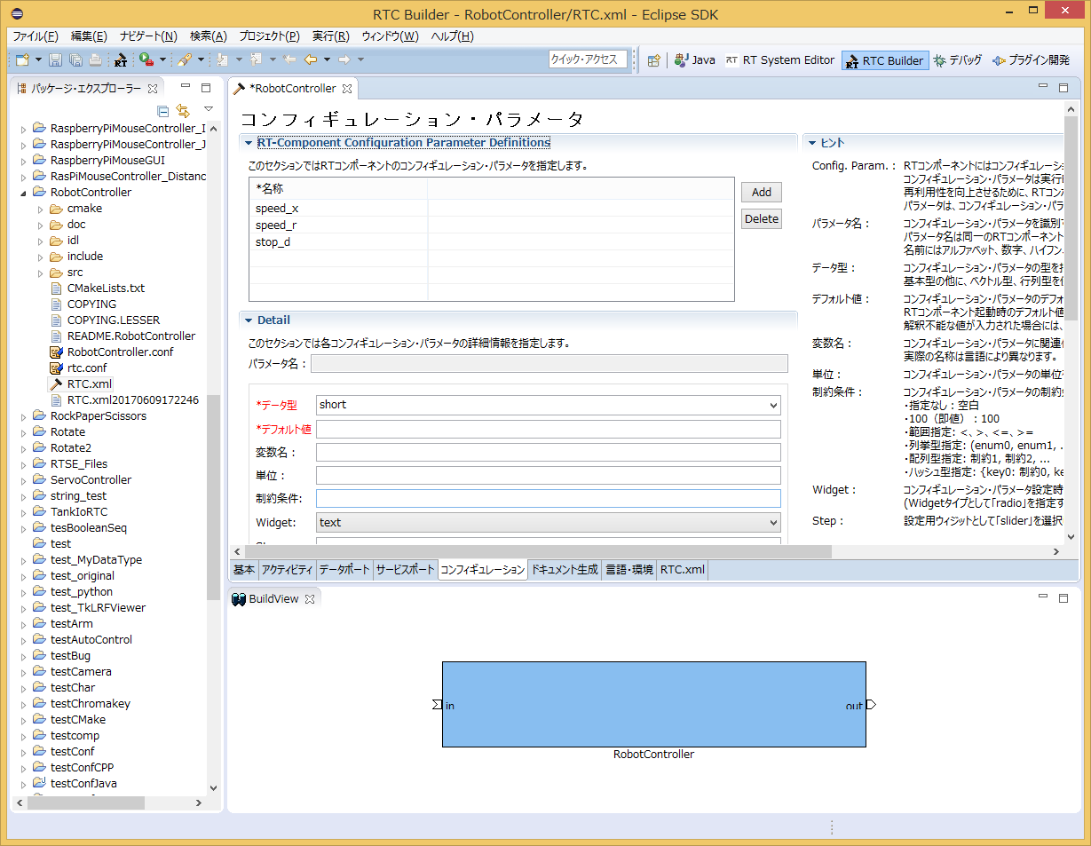
Next, select the “Configuration” tab and enter the Configuration information based on the specifications defined earlier.
Constraints and Widgets are used to change values through GUI elements such as sliders, spin buttons, and radio buttons when displaying component configuration parameters in RTSystemEditor.
The forward velocity speed_x and rotational velocity speed_r will be controllable using sliders.
- speed_x
- Name: speed_x
- Data Type: double
- Default Value: 0.0
- Constraint: -1.5<x<1.5
- Widget: slider
- Step: 0.01
- speed_r
- Name: speed_r
- Data Type: double
- Default Value: 0.0
- Constraint: -2.0<x<2.0
- Widget: slider
- Step: 0.01
- stop_d
- Name: stop_d
- Data Type: int
- Default Value: 30
- Widget: text
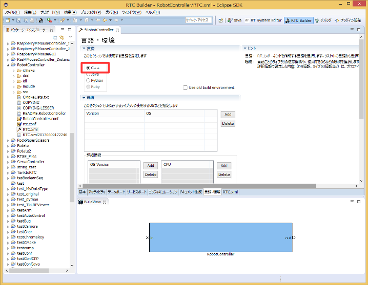
Next, select the “Language / Environment” tab and choose the programming language.
In this tutorial, select C++ (language). Note that the Language / Environment field has no default value. If you forget to specify a language, an error will occur during code generation, so be sure to specify the language.
Finally, click the [Generate Code] button on the “Basic” tab to generate the component template.
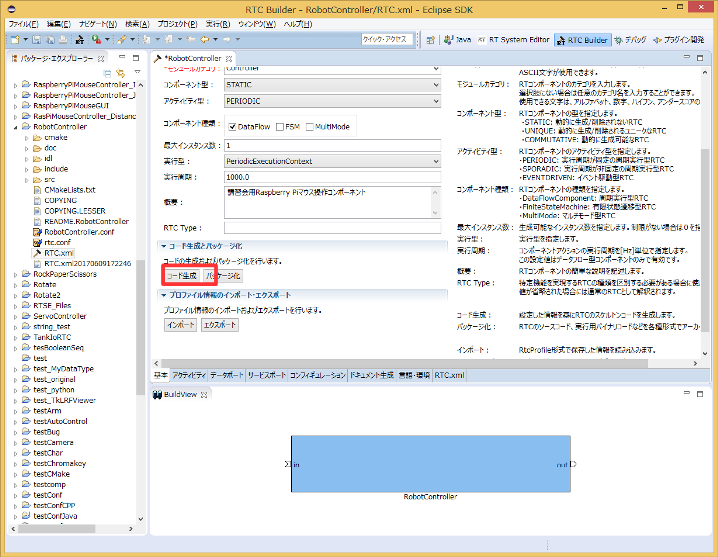
* The generated code files are created inside the workspace folder specified when Eclipse was started. You can check the current workspace from [File] > [Switch Workspace…].
Generating Files Required for Building with CMake
The code generated by RTC Builder includes a CMakeLists.txt file used to generate various files required for building with CMake.
By using CMake, project files, solution files, Makefiles, and other build-related files can be automatically generated from CMakeLists.txt.
Using CMake (cmake-gui)
Use CMake to configure the build environment.
First, start CMake (cmake-gui).
$ cmake-gui
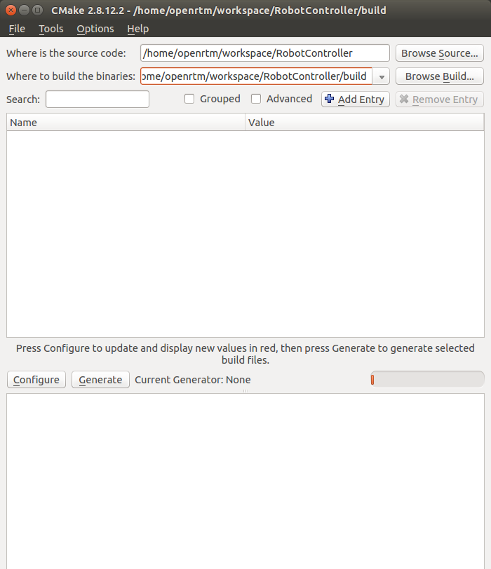
At the top of the screen, there are the following text boxes. Specify the source code location (where CMakeLists.txt exists) and the build directory.
- Where is the source code
- Where to build the binaries
The source code location is the directory where the RobotController component source code was generated and where CMakeLists.txt exists.
By default, it is:
<Workspace Directory>/RobotController
You can also set this directory by dragging and dropping it from the file explorer into cmake-gui instead of entering it manually.
The build directory is the location where project files, object files, and binaries generated during the build process are stored.
The location is arbitrary, but it is recommended to specify a RobotController subdirectory with an easy-to-understand name, such as:
<Workspace Directory>/RobotController/build
| Where is the source code | /home/username/RobotController |
|---|---|
| Where to build the binaries | /home/username/RobotController/build |
After specifying the directories, click the [Configure] button below.
A dialog similar to the one below will appear. Select the type of project you want to generate.
For this tutorial, select CodeBlocks - Unix Makefiles.
If you do not use Code::Blocks, select Unix Makefiles instead.
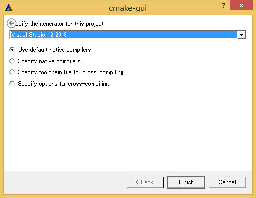
If you do not use cmake-gui, you can generate the files using the following commands.
 $ mkdir build
 $ cd build
 $ cmake .. -G "CodeBlocks - Unix Makefiles"
Click [Finish] in the dialog to start configuration.
If there are no problems, Configuring done will be displayed in the log window at the bottom.
Next, click the [Generate] button.
When Generating done is displayed, generation of project files, solution files, and related files is complete.
Note that CMake generates cache files during the Configure stage. If you change settings or modify the environment due to troubleshooting, select:
[File] > [Delete Cache]
Delete the cache and then run Configure again from the beginning.
Editing Header and Source Files
Next, start Code::Blocks by double-clicking RobotController.cbp in the build directory specified earlier.
Edit the header file (include/RobotController/RobotController.h) and source file (src/RobotController.cpp).
You can open the editor by clicking RobotController.h and RobotController.cpp from the Projects view in Code::Blocks.
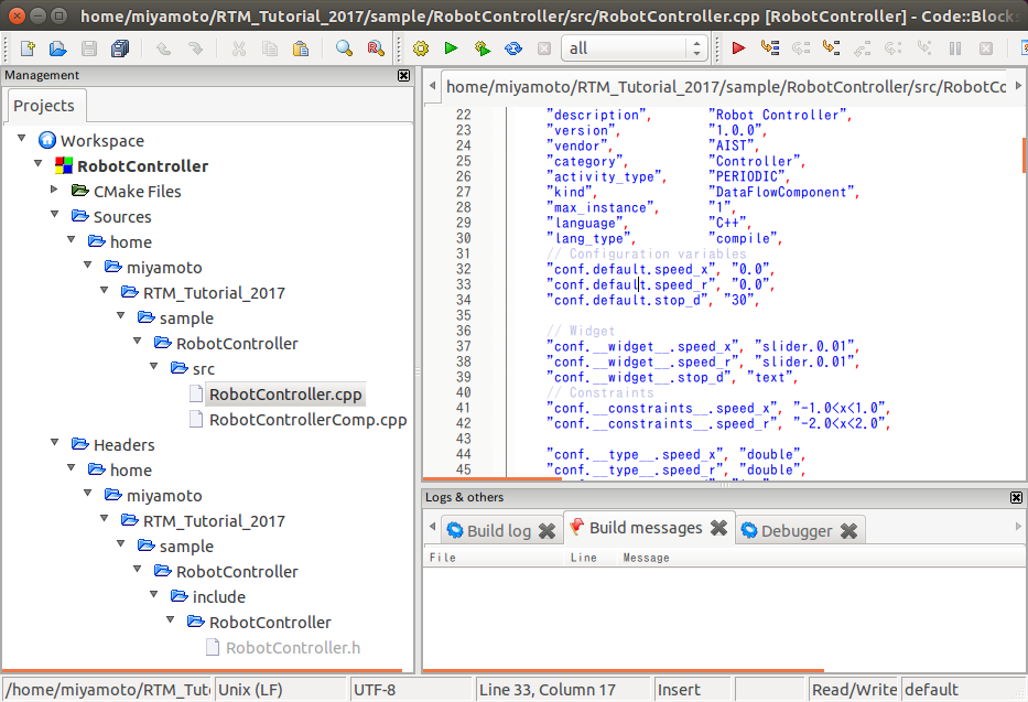
On 64-bit environments, Code::Blocks may sometimes behave unstably. In that case, disabling the plugin called “code completion” may resolve the issue.
Select:
Plugins > Manage plugins…
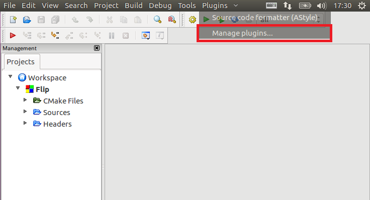
Select code completion and click the [Disable] button.
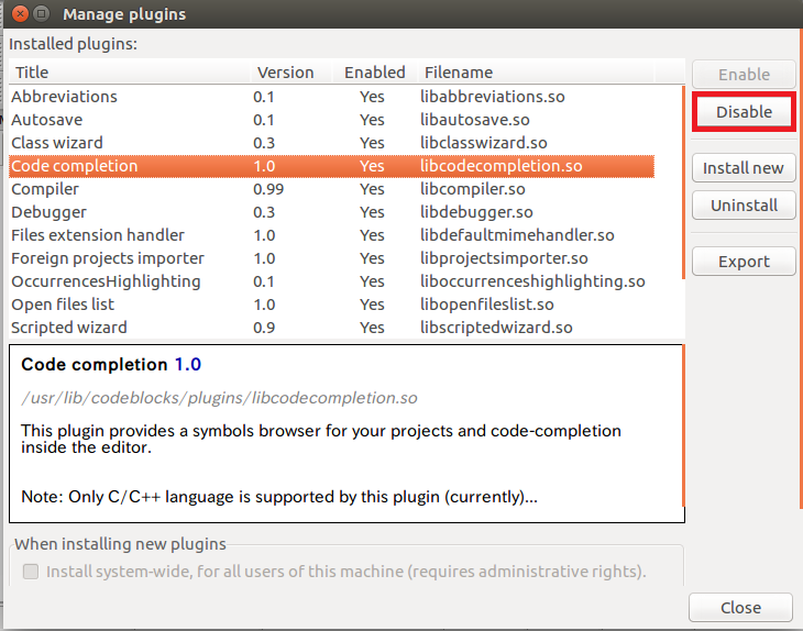
If Code::Blocks does not work correctly, try this procedure.
Implementing Activity Processing
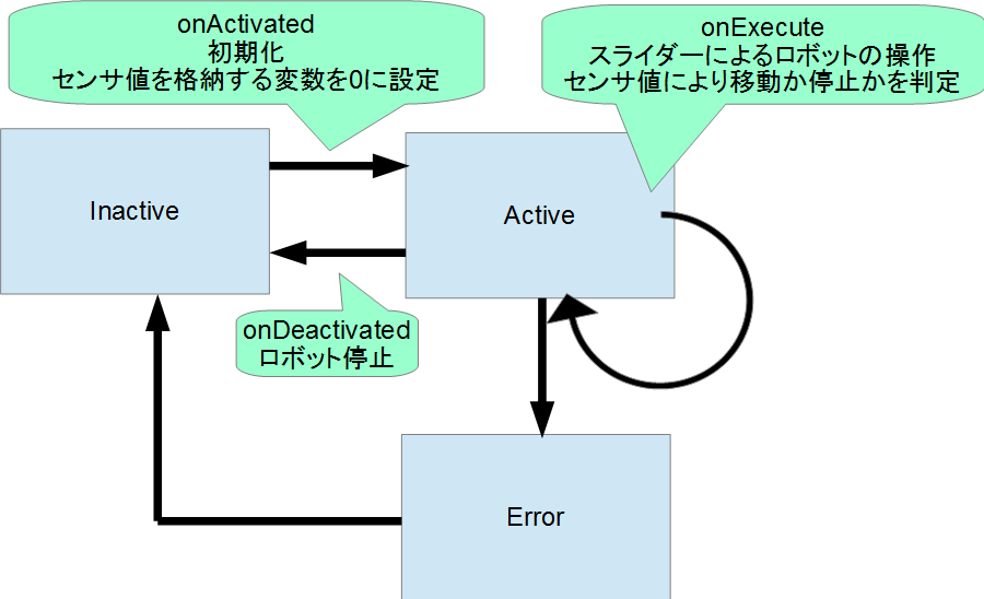
In the RobotController component, the configuration parameters (speed_x, speed_y) are controlled using sliders, and their values are output as target velocity through the OutPort (out).
Values input through the InPort (in) are stored in variables, and the robot is stopped when any value exceeds a specified threshold.
The processing performed in onActivated(), onExecute(), and onDeactivated() is shown below.
Editing the Header File (RobotController.h)
Declare the variable sensor_data to temporarily store sensor values.
   private:
 	 double sensor_data[4];	//センサー値を一時格納する変数
Editing the Source File (RobotController.cpp)
Implement onActivated(), onDeactivated(), and onExecute() as shown below.
 RTC::ReturnCode_t RobotController::onActivated(RTC::UniqueId ec_id)
 {
 	//センサー値初期化
 	for (int i = 0; i < 4; i++)
 	{
 		sensor_data[i] = 0;
 	}

   return RTC::RTC_OK;
 }
 RTC::ReturnCode_t RobotController::onDeactivated(RTC::UniqueId ec_id)
 {
 	//ロボットを停止する
 	m_out.data.vx = 0;
 	m_out.data.va = 0;
 	m_outOut.write();

   return RTC::RTC_OK;
 }
 RTC::ReturnCode_t RobotController::onExecute(RTC::UniqueId ec_id)
 {
 	//入力データの存在確認
 	if (m_inIn.isNew())
 	{
 		//入力データ読み込み
 		m_inIn.read();
 		for (int i = 0; i < m_in.data.length(); i++)
 		{
 			//入力データ格納
 			if (i < 4)
 			{
 				sensor_data[i] = m_in.data[i];
 			}
 		}
 	}

 	//前進するときのみ停止するかを判定
 	if (m_speed_x > 0)
 	{
 		for (int i = 0; i < 4; i++)
 		{
 			//センサ値が設定値以上か判定
 			if (sensor_data[i] > m_stop_d)
 			{
 				//センサ値が設定値以上の場合は停止
 				m_out.data.vx = 0;
 				m_out.data.va = 0;
 				m_outOut.write();
 				return RTC::RTC_OK;
 			}
 		}
 	}
 	//設定値以上の値のセンサーが無い場合はコンフィギュレーションパラメーターの値で操作
 	m_out.data.vx = m_speed_x;
 	m_out.data.va = m_speed_r;
 	m_outOut.write();
   return RTC::RTC_OK;
 }
Building with Code::Blocks
Running the Build
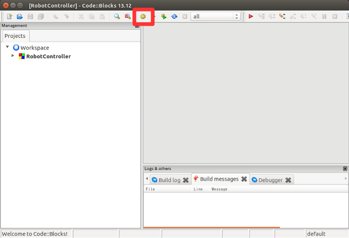
Click the [Build] button in Code::Blocks to build the project.
Verifying the Operation of the RobotController Component
Connect the RobotController component you created to the simulator component and verify that it operates correctly.
Starting the Name Service
Start the Name Service, which is used to register component references.
$ rtm-naming
Starting the RobotController Component
Start the RobotController component.
Run the RobotControllerComp executable located in the RobotController/build/src directory.
$ RobotControllerComp
Starting the Simulator Component
Move to the directory where the RaspberryPiMouseSimulator component was installed, and start it using the following command:
$ src/RaspberryPiMouseSimulatorComp
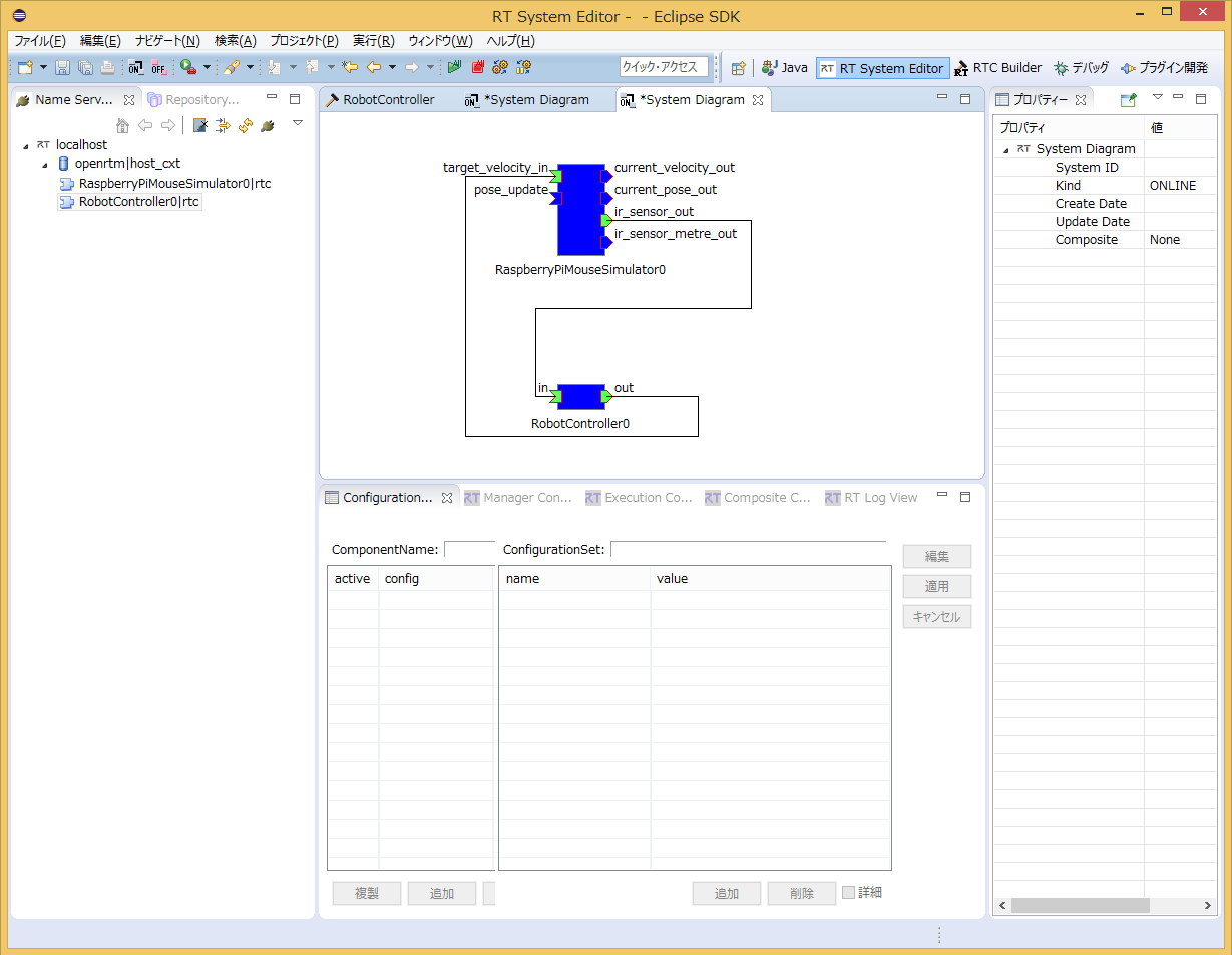
Connecting the Components
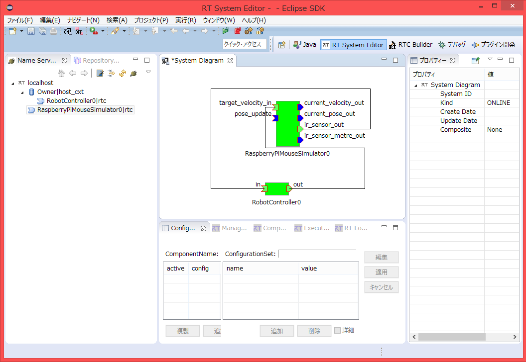
In RTSystemEditor, connect the RobotController component and the RaspberryPiMouseSimulator component as shown below.
Activating the Components
Click the [All Activate] icon located at the top of RTSystemEditor to activate all components.
If activation succeeds, the components will be displayed in light green as shown below.
Operation Check
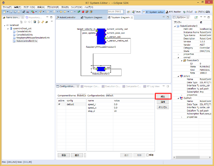
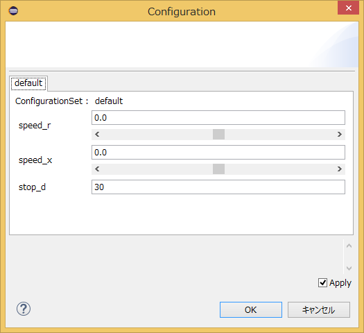
You can modify configuration parameters by clicking the [Edit] button in the Configuration View, as shown below.
Adjust the sliders and verify that you can control the Raspberry Pi Mouse in the simulator.
Verifying Operation on the Actual Hardware
If a physical Raspberry Pi Mouse is available during the workshop, you can also test the component on the real robot.
The procedure is as follows:
- Power on the Raspberry Pi Mouse
- Connect to the Raspberry Pi Mouse access point
- Connect the ports
- Activate the components
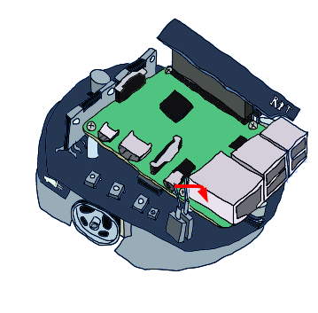
Powering On the Robot
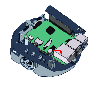
The Raspberry Pi Mouse has two power switches:
- Raspberry Pi power switch
- Motor power switch
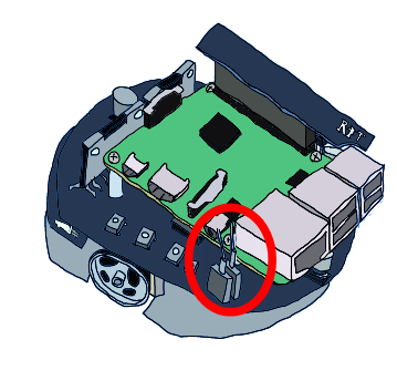
Turn on the inner power switch to start the Raspberry Pi.
Powering Off
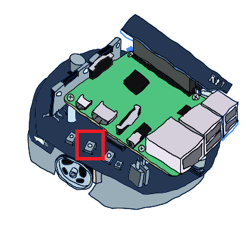
Do not turn off the Raspberry Pi by directly switching off the power.
To shut it down properly:
- Press and hold the center button of the three buttons for several seconds.
- Shutdown will begin.
- Wait approximately 10 seconds for Raspbian to shut down completely.
- Then turn off the power switch.
Connecting to the Access Point
The SSID and password are printed on a label attached to the Raspberry Pi Mouse.
Connect your PC to that wireless network.
Note
If the network connection changes, registration of components with the Name Service or port connections may fail. In that case, stop all Name Service and component processes and restart them.
If the Name Service and components were started after switching networks, restarting them is not necessary.
Adding the Name Server
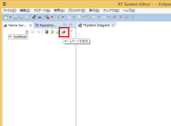
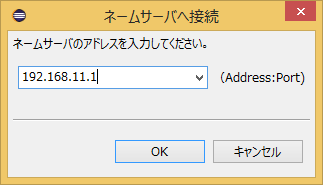
Next, click the [Add Name Server] button in RTSystemEditor and add:
192.168.11.1
The following two RTCs should become visible:
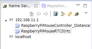
RaspberryPiMouseRTC is an RT Component for controlling the Raspberry Pi Mouse, developed by the Robot System Design Laboratory at Meijo University.
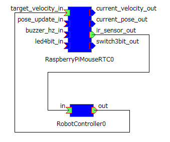
Connecting the Ports
In RTSystemEditor, connect RaspberryPiMouseRTC and RobotController as shown below.
Turning On the Motor Power
Before operating the robot, turn on the motor power switch.
It is recommended to turn off the motor power whenever it is not needed.
Activation
After activating the RTCs, you will be able to control the Raspberry Pi Mouse.